

A Lidar for Rendezvous and Docking between Space Vehicles
A laser radar, rendezvous and docking technology, applied in the field of spacecraft measurement and control, can solve the problems of not providing relative motion speed, relative angular velocity measurement functions, etc., to achieve the effect of ensuring attitude control
Active Publication Date: 2013-02-13
NO 27 RES INST CHINA ELECTRONICS TECH GRP
View PDF0 Cites 24 Cited by
- Summary
- Abstract
- Description
- Claims
- Application Information
AI Technical Summary
Problems solved by technology
In addition, the laser radar developed by Jena Optics for the Mars exploration mission of the European Space Agency is currently in the ground test stage. The working distance is 5km to 1km, the field of view is 20°×20°, and the data rate is 1Hz. Scanning imaging tracking, does not provide relative movement speed, relative angular velocity measurement function
Method used
View moreImage
Smart ImageViewing Examples

Examples
Embodiment Construction
Login to View More PUM
 Abstract
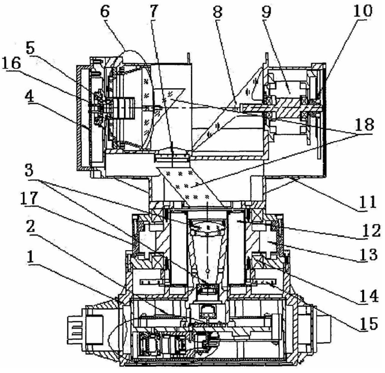
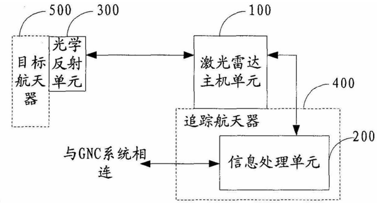
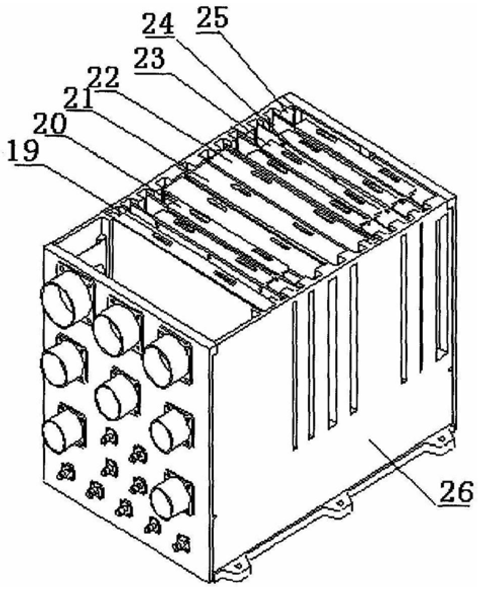
The invention discloses a laser radar used for rendezvous and docking between space spacecraft. Under the action of a control signal sent by an information processing unit, a laser radar host unit scans and detects an optical reflection unit by emitting pulsed laser light, and The detection data signal is returned to the information processing unit; the optical reflection unit reflects the pulsed laser for scanning and detection; the information processing unit sends a control signal to the laser radar host unit; the target spacecraft is captured according to the detection data signal returned by the laser radar host unit, and is transmitted through the laser The radar host unit tracks the captured target spacecraft. The invention realizes the scanning, capture and stable tracking of the target spacecraft with a long distance of 0.8m to 20km and a large field of view of 80°×105°, and the accuracy of scanning measurement can reach 0.05°, effectively ensuring the rendezvous and docking stage of the two spaceflights. Attitude control between devices to complete the rendezvous and docking task.
Description
A Lidar for Rendezvous and Docking between Space Vehicles technical field The invention relates to the technical field of spacecraft measurement and control, in particular to a laser radar used for rendezvous and docking between space spacecraft. Background technique Lidar can measure parameters such as close range, angle, speed, and attitude, and it is small in size, light in weight, and low in power consumption. The United States, Russia, the European Space Agency, and Japan are actively developing lidar for space rendezvous and docking . The laser radar developed by Jena Optics for space spacecraft rendezvous and docking is representative. In 2008, lidar played a key role in the first rendezvous and docking mission between the European Space Agency's automated transfer vehicle and the International Space Station. The working distance is from 730m to 1m, the maximum field of view is 40°×40°, the data rate is 1Hz at long distance, 3Hz or 2Hz at short distance, and the ...
Claims
Login to View More Application Information
Patent Timeline
 IPC IPC(8): G01S17/88
Inventor薛海中张清源屈恒阔沈严董光焰刘恩海李磊李冬梅岳永坚李明山吴登喜张文平李勇董景宇邢旭东赵春生杨武赵明福叶鹏程
OwnerNO 27 RES INST CHINA ELECTRONICS TECH GRP