Eureka AIR delivers breakthrough ideas for toughest innovation challenges, trusted by R&D personnel around the world.

Automatic cutter taking and placing cabinet

A technology for cabinets and knives, applied in the field of cabinets, can solve the problems of insufficient manpower and low degree of cabinet mechanization, and achieve the effect of simple use.

Inactive Publication Date: 2017-01-25
蓝玉
View PDF0 Cites 1 Cited by
  • Summary
  • Abstract
  • Description
  • Claims
  • Application Information

AI Technical Summary

Problems solved by technology

[0002] Cabinets, also known as "family kitchen furniture", "cabinet soldiers", etc.; are family civil facilities that integrate cooking, washing, storage, oil fume and other comprehensive functions in the family kitchen; she was first developed by the Japanese Corina Cabinet Co., Ltd. The concept put forward by Katsuko Inoue, the company----is the physical carrier of various kitchen utensils and kitchen appliances in the modern integrated kitchen and the artistic carrier of kitchen design ideas, so she is the main body of the modern integrated kitchen, in a sense We can even equate the design of the overall kitchen with the design of the overall cabinet. The cabinet is composed of wall cabinets, floor cabinets, countertops and various functional hardware accessories. However, the existing cabinets are not highly mechanized. When a person cooks at home, Often due to lack of manpower, it causes confusion, so we need an intelligent technology for when a person is cooking in the kitchen, due to lack of manpower, it is necessary to walk around to choose kitchen utensils

Method used


Image

  • Automatic cutter taking and placing cabinet
  • Automatic cutter taking and placing cabinet
  • Automatic cutter taking and placing cabinet

Examples


Embodiment Construction

[0015] The following will clearly and completely describe the technical solutions in the embodiments of the present invention with reference to the accompanying drawings in the embodiments of the present invention. Obviously, the described embodiments are only some, not all, embodiments of the present invention. Based on the embodiments of the present invention, all other embodiments obtained by persons of ordinary skill in the art without making creative efforts belong to the protection scope of the present invention.

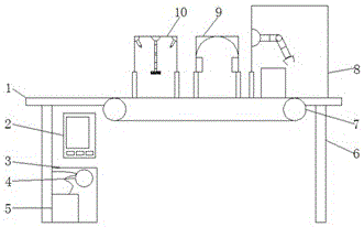
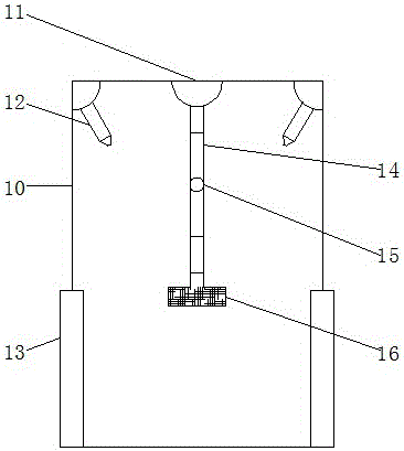
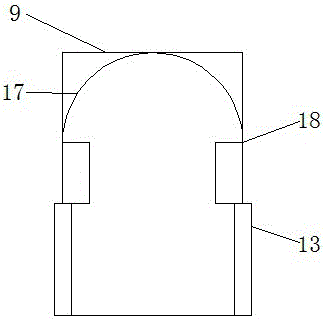
[0016] see Figure 1-4 , the present invention provides an automatic tool picking and placing cabinet, comprising a working body 1, a cabinet 8, a disinfection device 9 and a cleaning device 10, characterized in that: the cabinet 8 is installed on the upper right side of the working body 1, and the disinfection device 9 is installed on the left side of the cabinet 8 side, the cleaning device 10 is installed on the left side of the disinfection device 9, the co...


PUM


Abstract

The invention discloses an automatic tool picking and placing cabinet, which comprises a working body, a cabinet, a disinfection device and a cleaning device. The cabinet is installed on the upper right of the working body, the disinfection device is installed on the left side of the cabinet, and the cleaning device is installed on the On the left side of the disinfection device, a control device is installed at the bottom left of the working body, a power device is installed at the bottom of the control device, and a PLC electric control unit is installed above the power device. The control unit is electrically connected. A rotating device is installed on the upper inner surface of the cleaning device. A telescopic rod is installed on the cleaning device through the rotating device. A cleaning drum is installed at the bottom of the telescopic rod. A sterilizer is installed below the two ends of the arc-shaped heating plate, and a knife rest is installed on the left side of the inside of the cabinet. The automatic tool pick-and-place cabinet of the present invention adopts automation technology, and is simple and convenient to use.

Description

technical field [0001] The invention relates to the field of cabinets, in particular to an automatic tool pick-and-place cabinet. Background technique [0002] Cabinets, also known as "family kitchen furniture", "cabinet soldiers", etc.; are family civil facilities that integrate cooking, washing, storage, oil fume and other comprehensive functions in the family kitchen; she was first developed by the Japanese Corina Cabinet Co., Ltd. The concept put forward by Katsuko Inoue, the company----is the physical carrier of various kitchen utensils and kitchen appliances in the modern integrated kitchen and the artistic carrier of kitchen design ideas, so she is the main body of the modern integrated kitchen, in a sense We can even equate the design of the overall kitchen with the design of the overall cabinet. The cabinet is composed of wall cabinets, floor cabinets, countertops and various functional hardware accessories. However, the existing cabinets are not highly mechanized. ...

Claims


Application Information

Patent Timeline
Patent Type & Authority Applications(China)
IPC IPC(8): A47B77/08A47B77/18A47B97/00
CPCA47B77/08A47B77/18A47B97/00
Inventor 蓝玉
Owner 蓝玉
Why Eureka
Eureka Blog
Learn More