
Ejector with telescopic nozzles

An ejector and telescopic technology, applied in the field of nozzle retractable ejector, can solve the problems of affecting the fracturing effect, unsatisfactory perforation depth, and difficulty in ensuring the effectiveness of isolation, so as to improve the fracturing effect and increase reliability. The effect of reducing the cost of fracturing

Inactive Publication Date: 2017-01-25
PETROCHINA CO LTD
View PDF10 Cites 2 Cited by
  • Summary
  • Abstract
  • Description
  • Claims
  • Application Information

AI Technical Summary

Problems solved by technology

[0006] The purpose of the present invention is to overcome the problems of unsatisfactory perforation depth of existing hydraulic injection, difficulty in guaranteeing sealing effectiveness, and affecting fracturing effect

Method used


Image

  • Ejector with telescopic nozzles
  • Ejector with telescopic nozzles

Examples


Embodiment 1

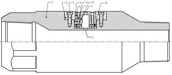
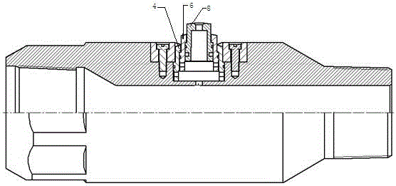
[0025] In order to overcome the problems of unsatisfactory perforation depth of existing hydraulic injection, difficulty in guaranteeing sealing effectiveness, and affecting fracturing effect, this embodiment provides a method such as figure 1 and figure 2 The nozzle retractable injector shown includes an injector body 1, and the injector body 1 is provided with a reserved hole 11, and a telescopic nozzle is arranged at the reserved hole 11, and the telescopic nozzle is arranged from the outside to the inside The outer layer nozzle 4, the middle layer nozzle 6 and the inner layer nozzle 8 are sequentially set, and the lower parts of the outer layer nozzle 4, the middle layer nozzle 6 and the inner layer nozzle 8 are fixed by nozzle connecting pins 10, and the outer layer nozzle 4 A large-diameter sealing ring 5 is provided between the injector body 1, a medium-diameter sealing ring 7 is provided between the outer nozzle 4 and the middle nozzle 6, and a small-diameter sealing ...

Embodiment 2

[0029] This embodiment provides an injector with a retractable nozzle, which includes an injector body 1, a reserved hole 11 is arranged on the injector body 1, and a telescopic nozzle is arranged at the reserved hole 11, and the telescopic nozzle is composed of The outer layer nozzle 4, the middle layer nozzle 6 and the inner layer nozzle 8 are sequentially set from the outside to the inside. The lower parts of the outer layer nozzle 4, the middle layer nozzle 6 and the inner layer nozzle 8 are fixed by nozzle connecting pins 10. A large-diameter sealing ring 5 is provided between the outer nozzle 4 and the injector body 1, a medium-diameter sealing ring 7 is provided between the outer nozzle 4 and the middle nozzle 6, and a middle-diameter sealing ring 7 is provided between the middle nozzle 6 and the inner nozzle 8. A small-diameter sealing ring 9 is arranged between them, and the outer layer nozzle 4 is pressed tightly by the gland 2, and the gland 2 is fixed on the injecto...


PUM


Abstract

The invention provides an ejector with telescopic nozzles. The ejector comprises an ejector body, preservation holes are formed in the ejector body, the telescopic nozzles are arranged in the preservation holes and are composed of an outer layer nozzle, a middle layer nozzle and an inner layer nozzle which are arranged in a sleeving mode from outside to inside in sequence, the lower parts of the outer layer nozzle, the middle layer nozzle and the inner layer nozzle are fixed through nozzle connecting pins, a large-diameter sealing ring is arranged between the outer layer nozzle and the ejector body, a middle-diameter sealing ring is arranged between the outer layer nozzle and the middle layer nozzle, a small-diameter sealing ring is arranged between the middle layer nozzle and the inner layer nozzle, the outer layer nozzle is pressed through a gland, and the gland is fixed to the ejector body through gland pins. The ejector can carry out ejecting and feeding at the same time, a radial horizontal hole with a certain hole diameter and depth is finally formed, and the accuracy of opening a crack at a fixed point of a wellbore wall and the depth of an ejection hole are improved; the influence of the stress of a near wellbore area is reduced, the partial pressure probability is increased, and the reliability of hydrofracture self-packing is improved; the purposes of improving fracturing effects and reducing the fracturing cost are achieved.

Description

technical field [0001] The invention belongs to the technical field of hydraulic fracturing of oil and gas wells in low-permeability and ultra-low-permeability oil reservoirs, and in particular relates to a retractable nozzle injector. Background technique [0002] At present, increasing production of new wells, stabilizing production of old wells, and measures to increase oil production all depend on conventional production stimulation measures such as fracturing and acidizing to varying degrees. Perforation, as the main link, is directly related to oil and gas well productivity. After several decades of development, the perforation technology has made significant progress, especially since the 1990s, the perforation technology has developed rapidly. [0003] At present, a number of perforation technologies such as fire perforation, multi-pulse compound perforation, high-energy gas perforation, and hydrojet have emerged as the times require, but most of them have problems s...

Claims


Application Information

Patent Timeline
Patent Type & Authority Applications(China)
IPC IPC(8): E21B43/114E21B43/26
Inventor 赵粉霞邵媛付钢旦张华光王在强任国富赵广民郭思文赵敏琦薛晓伟
Owner PETROCHINA CO LTD
Learn More