
High-speed EMU wheel vibration test bench

A technology for high-speed EMUs and vibration test benches, applied in vibration testing, testing of machine/structural components, measuring devices, etc., can solve problems such as the lack of test platforms, and achieve low cost, easy disassembly, and easy maintenance.

Active Publication Date: 2019-01-04
ZHEJIANG SCI-TECH UNIV
View PDF9 Cites 0 Cited by
  • Summary
  • Abstract
  • Description
  • Claims
  • Application Information

AI Technical Summary

Problems solved by technology

Although my country's high-speed rail has developed rapidly in recent years, there is a lack of test platforms related to high-speed rail.

Method used


Image

  • High-speed EMU wheel vibration test bench
  • High-speed EMU wheel vibration test bench
  • High-speed EMU wheel vibration test bench

Examples


Embodiment Construction

[0021] The present invention will be further described below in conjunction with the accompanying drawings and embodiments.

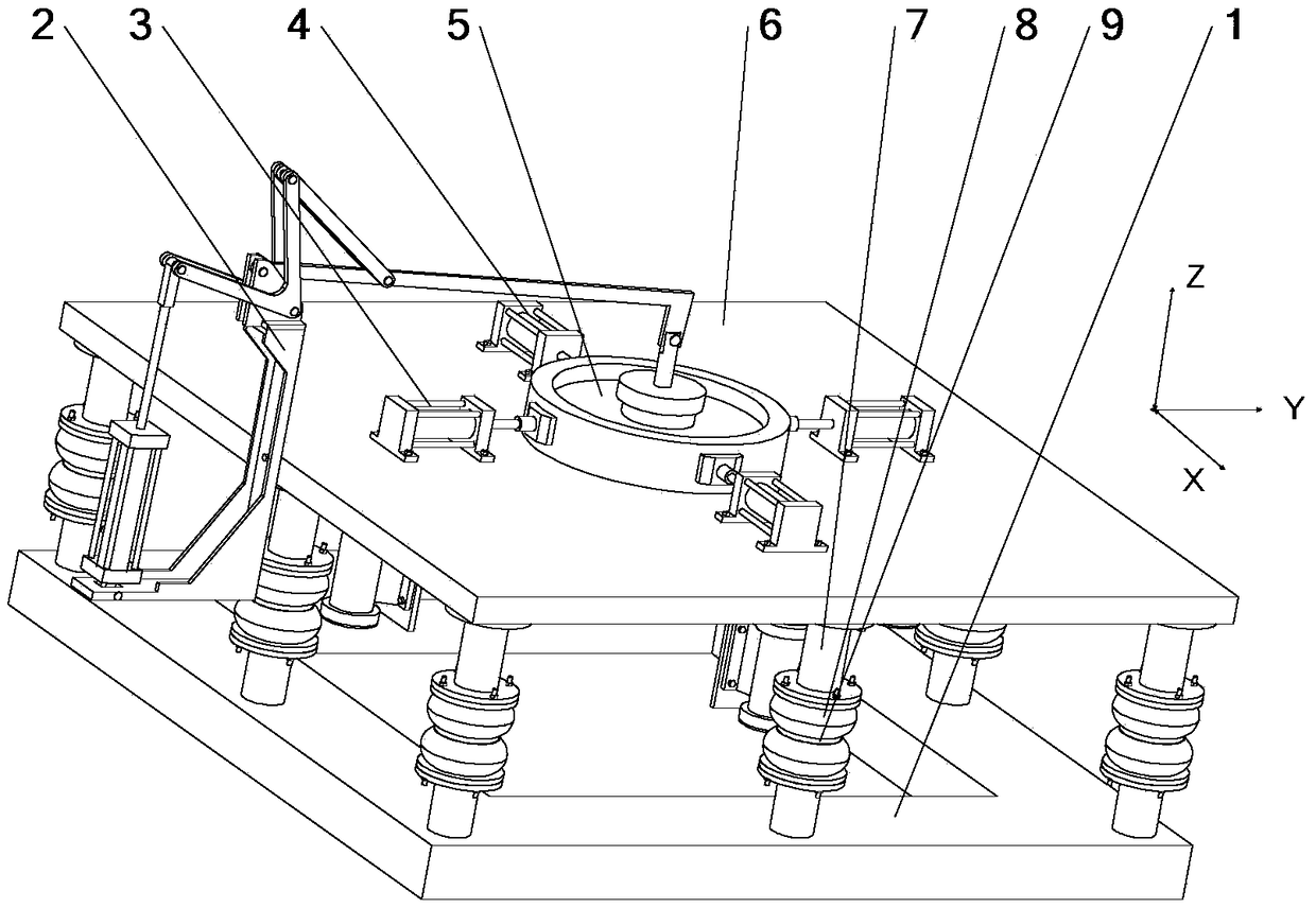
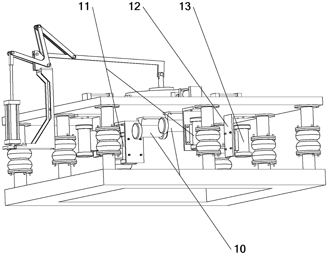
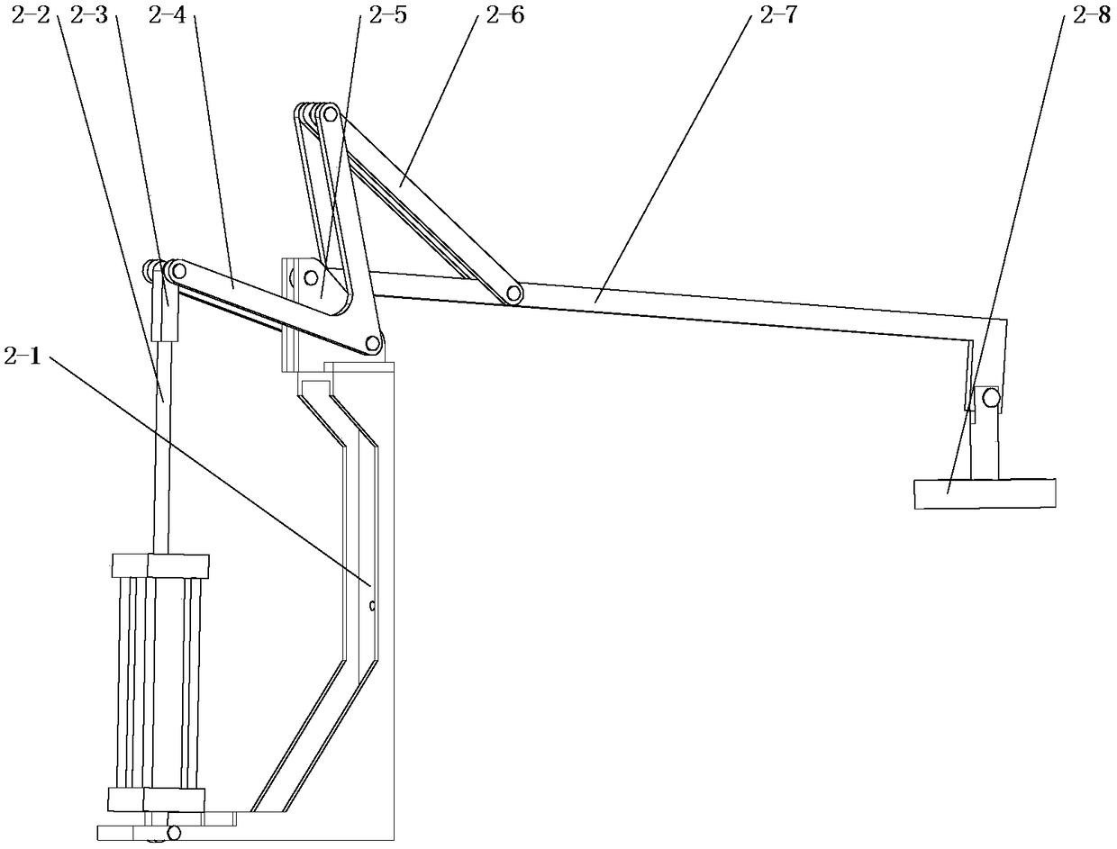
[0022] Such as figure 1 and 2 As shown, the high-speed EMU wheel vibration test bench is composed of a controller, a Z-direction clamping mechanism 2, a Y-direction clamping mechanism 3, an X-direction clamping mechanism 4 and a vibration table; two Y-direction clamping mechanisms 3 and two The X-direction clamping mechanisms 4 are evenly distributed along the circumference, and the Y-direction clamping mechanisms 3 and the X-direction clamping mechanisms 4 are alternately arranged. The controller controls the vertical hydraulic cylinder 2-2 of the Z-direction clamping mechanism and the horizontal hydraulic cylinder 3-2 of the Y-direction clamping mechanism 3 and X-direction clamping mechanism 4 to clamp or loosen the high-speed EMU wheel 5 , and control the start and stop of the X-direction vibration motor 11, Z-direction vibration motor 10 and Y-dir...


PUM


Abstract

The invention discloses a wheel vibration test bench for a high-speed EMU. At present, there is no wheel vibration test bench for high-speed EMUs. The invention includes a Z-direction clamping mechanism, a Y-direction clamping mechanism, an X-direction clamping mechanism and a vibrating table; the X-direction clamping mechanism, the Y-direction clamping mechanism and the Z-direction clamping mechanism are used for clamping the high-speed EMU wheels, The high-speed EMU wheels are fixed on the vibrating plate; the vibrating table is used to provide vibration excitation, vibration frequency and vibration amplitude. The invention can be used to verify whether the structural strength of the high-speed EMU wheels meets the requirements under vibration conditions, verify whether the reliability of the high-speed EMU wheels meets the requirements under long-term vibration conditions, and test the high-speed EMU wheels under long-term vibration conditions. Long service life, low cost, small space occupation, easy disassembly and maintenance.

Description

technical field [0001] The invention belongs to the technical field of vibration tests, in particular to a wheel vibration test bench for high-speed train sets. Background technique [0002] During the running of high-speed EMU trains, wheel vibrations will be caused by track irregularities, and whether the structural strength of the wheels meets the requirements under vibration conditions and whether the wheels are reliable under long-term vibration conditions need to be tested and verified. Designers optimize and perfect the wheel structure. Although my country's high-speed rail has developed rapidly in recent years, there is a considerable lack of test platforms related to high-speed rail. Contents of the invention [0003] The purpose of the present invention is to provide a high-speed EMU wheel vibration test rig for the lack of a high-speed EMU wheel test platform, which can effectively clamp the high-speed EMU wheel, and adjust the vibration frequency, vibration ex...

Claims


Application Information

Patent Timeline
Patent Type & Authority Patents(China)
IPC IPC(8): G01M7/06
CPCG01M7/06
Inventor 秦玉冬胡明张鹏赵永翔周迅钱萍陈文华
Owner ZHEJIANG SCI-TECH UNIV
Learn More