Supercharge Your Innovation With Domain-Expert AI Agents!

A control method and device for a three-phase three-wire rectifier circuit

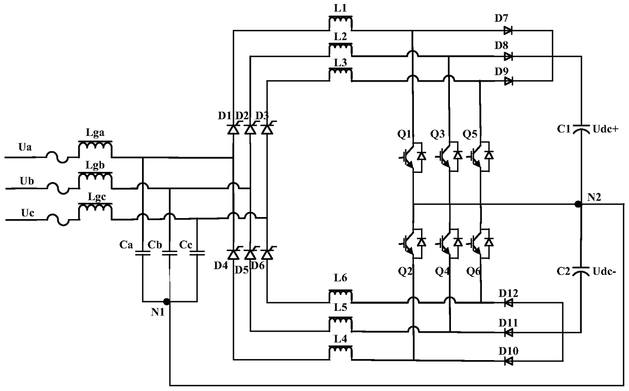
A rectifier circuit, three-phase three-wire technology, used in electrical components, output power conversion devices, AC power input conversion to DC power output and other directions, can solve the problems of uncontrollable, high half bus voltage amplitude, and high bus voltage

Active Publication Date: 2018-09-25
VERTIV CORP
View PDF5 Cites 0 Cited by
  • Summary
  • Abstract
  • Description
  • Claims
  • Application Information

AI Technical Summary

Problems solved by technology

[0007] The embodiment of the present invention provides a control method and equipment for a three-phase three-wire rectifier circuit, which is used to solve the problem that the half-bus voltage amplitude obtained before the BOOST circuit is not working after the thyristor is completely turned on in the current Vienna-like rectifier may be too high and Problems such as high and uncontrollable bus voltage after input high-voltage rectification

Method used


Image

  • A control method and device for a three-phase three-wire rectifier circuit
  • A control method and device for a three-phase three-wire rectifier circuit
  • A control method and device for a three-phase three-wire rectifier circuit

Examples


Embodiment 1

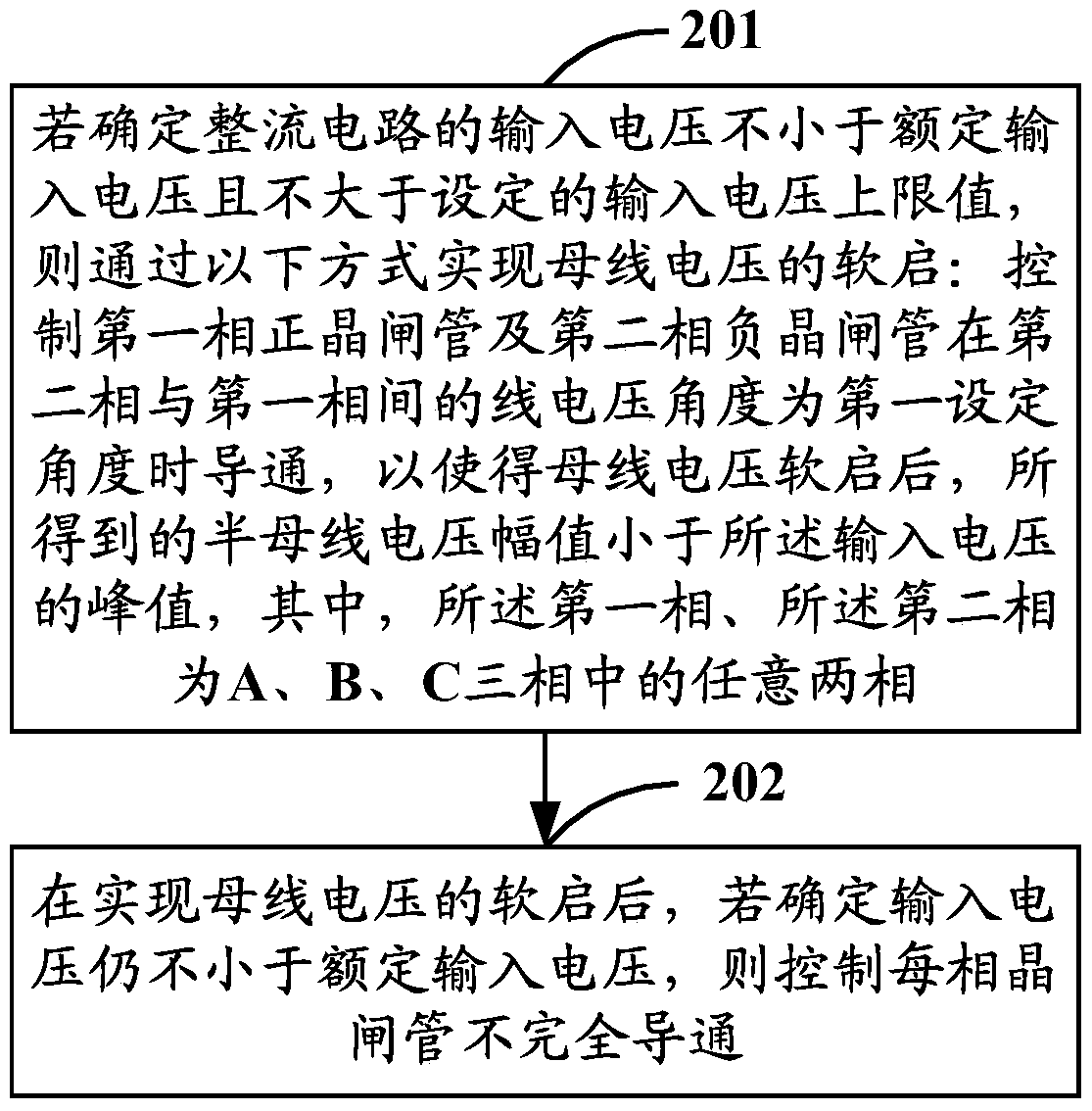
[0024] Embodiment 1 of the present invention provides a control method for a three-phase three-wire rectifier circuit, such as figure 2 As shown, it is a schematic flow chart of the control method of the three-phase three-wire rectifier circuit described in Embodiment 1 of the present invention, and the method may include the following steps:

[0025] Step 201: If it is determined that the input voltage of the three-phase three-wire rectifier circuit is not less than the rated input voltage and not greater than the set input voltage upper limit, the soft start of the bus voltage is realized by controlling the first phase positive thyristor and the second The phase-negative thyristor is turned on when the line voltage angle between the second phase and the first phase is the first set angle, so that after the bus voltage is soft-started, the obtained half-bus voltage amplitude is smaller than the peak value of the input voltage, wherein , the first phase and the second phase a...

Embodiment 2

[0064] Based on the same inventive concept, Embodiment 2 of the present invention provides a control device for a three-phase three-wire rectifier circuit. For the specific implementation of the control device, please refer to the relevant description in Embodiment 1 of the above-mentioned method. Figure 4 As shown, it is a schematic structural diagram of the control device described in Embodiment 2 of the present invention, and the control device may mainly include:

[0065] The input voltage judging module 41 can be used to judge whether the input voltage of the three-phase three-wire rectifier circuit is not less than the rated input voltage and not greater than the set input voltage upper limit;

[0066] The voltage soft-start control module 42 can be used to determine that the input voltage of the three-phase three-wire rectifier circuit is not less than the rated input voltage and not greater than the set input voltage upper limit according to the judgment result of the ...


PUM


Abstract

The invention discloses a control method and equipment of a three-phase three-wire rectifying circuit. The method is characterized in that when input voltage is not smaller than rated input voltage and not larger than a set input voltage upper limit, soft starting of bus voltage is achieved by following manners, to be more specific, a first-phase positive thyristor and a second-phase negative thyristor are controlled to be connected when the wire voltage angle between the second phase and the first phase is the first set angle to allow the amplitude of obtained semi-bus voltage to be smaller than the peak of the input voltage after the soft starting of the bus voltage, the first phase and the second phase are two optional phases of a phase A, a phase B and a phase C, and the problem of excessively high bus voltage is avoided; after the soft starting of the bus voltage, if the input voltage is still not smaller than the rated input voltage, each phase of thyristor is controlled to be incompletely connected, and accordingly the risk that the bus voltage is high and uncontrollable after high voltage is input for rectifying.

Description

technical field [0001] The invention relates to the technical field of circuit control, in particular to a control method and equipment for a three-phase three-wire rectifier circuit. Background technique [0002] Compared with the I-type three-level rectifier, the Vienna-like rectifier has the characteristics of fewer switching devices and lower cost, so it is widely used in high-voltage and high-power applications. [0003] Specifically, such as figure 1 As shown in FIG. 1 , it is a schematic diagram of a circuit topology structure of a common Vienna rectifier. Among them, Ua, Ub, and Uc are input phase voltages, Lga, Lgb, and Lgc are input side filter inductors, Ca, Cb, and Cc are input side filter capacitors, L1~L6 are boost inductors, C1, C2 are bus capacitors, D1 ~D6 is the input rectifier thyristor, D7~D12 is the BOOST (boost) circuit freewheeling diode, Q1~Q6 is the BOOST circuit switch tube, Udc+ is the positive bus voltage, Udc- is the negative bus voltage, N1 is...

Claims


Application Information

Patent Timeline
Patent Type & Authority Patents(China)
IPC IPC(8): H02M7/155
Inventor 卓清锋豆飞进李宗健付俊峰
Owner VERTIV CORP
Features
  • R&D
  • Intellectual Property
  • Life Sciences
  • Materials
  • Tech Scout
  • Unparalleled Data Quality
  • Higher Quality Content
  • 60% Fewer Hallucinations
Learn More