Deepwater drilling sand sampling robot

A deep-sea drilling and robot technology, which is applied in drilling equipment, underwater drilling, drill bits, etc., can solve the problems of low reliability of submarine drilling equipment, insufficient depth of drilling equipment, and complex structure.

Active Publication Date: 2017-02-01
NINGBO JIELIANG ROBOT TECH CO LTD
View PDF6 Cites 11 Cited by
  • Summary
  • Abstract
  • Description
  • Claims
  • Application Information

AI Technical Summary

Problems solved by technology

From the current point of view, the current status of deep-sea drilling and sampling technology at home and abroad is that domestic deep-sea drilling starts late and develops slowly, the reliability of submarine drilling equipment is low, and the depth of drilling equipment does not meet the requirements. Technology companies, this situation is very unfavorable to the country's strategic position in the marine industry; foreign deep-sea drilling mostly uses professional drilling ships or drilling platforms, which are equipped with drilling towers, drilling rigs and other equipment, with complex structures and huge costs
[0003] Drilling ships and drilling platforms have obvious disadvantages: they are greatly affected by sea wind and currents, and the stability of the platform cannot be guaranteed, and the drill pipe will also swing along with it, resulting in short effective operation time, low drilling success rate, and greatly increased service life of the drill pipe. shorten
When taking coring, because the drill pipe is very long, it is difficult to control the force applied when lifting the drill, and the fracture position of the sample is full of uncertainty, which even leads to multiple coring failures, which reduces the operation efficiency
Traditional drilling sampling also needs to take the sample out of the water surface for analysis, resulting in incomplete or deviation in various formation physical and mechanical parameters of the sample, thus affecting the detection results

Method used


Image

  • Deepwater drilling sand sampling robot
  • Deepwater drilling sand sampling robot

Examples


Embodiment Construction

[0020] In order to make the technical content disclosed in this application more detailed and complete, reference may be made to the drawings and the following various specific embodiments of the present invention, and the same symbols in the drawings represent the same or similar components. However, those skilled in the art should understand that the examples provided below are not intended to limit the scope of the present invention. In addition, the drawings are only for schematic illustration and are not drawn according to their original scale.

[0021] The specific implementation manners of various aspects of the present invention will be further described in detail below with reference to the accompanying drawings.

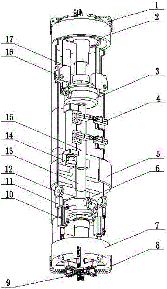
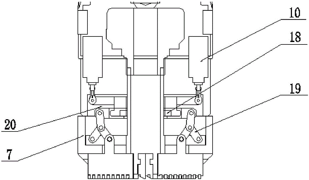
[0022] figure 1 It shows a schematic structural view of a deep-sea drilling and sampling robot according to an embodiment of the present invention, figure 2 Shows figure 1 Partial cross-sectional view of the front drill bit of the deep-sea drilling and ...


PUM


Abstract

The invention provides a deepwater drilling and sampling robot. The deepwater drilling and sampling robot comprises a front drilling unit, a rear drilling unit, a hydraulic telescopic device and a sample detecting unit. The front drilling unit comprises a first hydraulic motor, a front tool rest, fixed drill bits and variable drill bits, and is used for drilling and coring. The rear drilling unit comprises reaming bits, a rear tool rest and a second hydraulic motor, and is used for conducting reaming operation to clear roadblocks away through the reaming bits when the deepwater drilling and sampling robot returns. The hydraulic telescopic device is used for controlling the variable drill bits to expand and contract so as to achieve integration of drilling and coring. The sample detecting unit is used for analyzing and treating samples obtained, and sending experimental data back in real time. Compared with the prior art, integration of the drilling function and the coring function is achieved through expanding and contracting of the variable drill bits, the coring size is accurately controlled accordingly, a sea surface drilling platform is not needed, and the cost and time are reduced.

Description

technical field [0001] The invention relates to geological drilling equipment, in particular to a deep-sea drilling and sampling robot. Background technique [0002] The total area of ​​the earth's surface is about 510 million square kilometers, about 70% of which is ocean. The development and utilization of marine resources have been paid more and more attention by various countries, and the related marine resource exploration industry has become the core strategic field of many countries. The depth of the ocean can range from a few meters in the shallow sea to thousands of meters in the deep sea. Deep sea exploration and sampling are technically difficult, especially the equipment used for sampling is demanding, which is a major bottleneck in the exploration of marine resources. The deep sea is often rich in resources, and exploration is of great significance, and it is a hot spot in marine resource exploration. From the current point of view, the current status of deep-...

Claims


Application Information

Patent Timeline
Patent Type & Authority Applications(China)
IPC IPC(8): E21B49/00E21B7/12E21B47/001E21B10/32
CPCE21B7/12E21B10/322E21B47/001E21B49/001
Inventor 顿向明山磊高爱军
Owner NINGBO JIELIANG ROBOT TECH CO LTD
Why Eureka
Try Eureka