
Ultra-precision in-situ measurement device based on flexible probe and ultra-precision processing method

An in-situ measurement and ultra-precise technology, applied in the direction of metal processing equipment, measuring/indicating equipment, metal processing machinery parts, etc., can solve the obstacles to the integrated automation of processing, measurement and compensation processes, the system structure is not easy to miniaturize, and is not suitable for large Problems such as curvature and surface shape, to achieve the effect of ensuring offline measurement capability, breaking through the limitation of surface curvature measurement, and easy in-situ measurement

Active Publication Date: 2012-05-23
TIANJIN UNIV
View PDF0 Cites 0 Cited by
  • Summary
  • Abstract
  • Description
  • Claims
  • Application Information

AI Technical Summary

Problems solved by technology

Existing measurement technologies have the shortcomings of small scanning range, relatively simple measurement surface shape, and offline measurement, which will introduce secondary clamping and positioning errors during processing, and also hinder the integrated automation of processing, measurement, and compensation processes. Therefore, Nano-precision in-situ measurement system based on ultra-precision machine tools has become a research hotspot
The optical measurement method has the advantages of fast speed and non-damage, but due to the complex optical structure, the system structure is not easy to miniaturize, and it is difficult to achieve in-situ placement in the limited space of ultra-precision machine tools, which is also an important reason affecting its in-situ
At the same time, limited by the numerical aperture and field of view of the optical system, this optical non-contact method is not suitable for the measurement of large curvature surfaces

Method used


Image

  • Ultra-precision in-situ measurement device based on flexible probe and ultra-precision processing method
  • Ultra-precision in-situ measurement device based on flexible probe and ultra-precision processing method
  • Ultra-precision in-situ measurement device based on flexible probe and ultra-precision processing method

Examples


Embodiment Construction

[0024] The present invention will be further described below in conjunction with the accompanying drawings and embodiments.

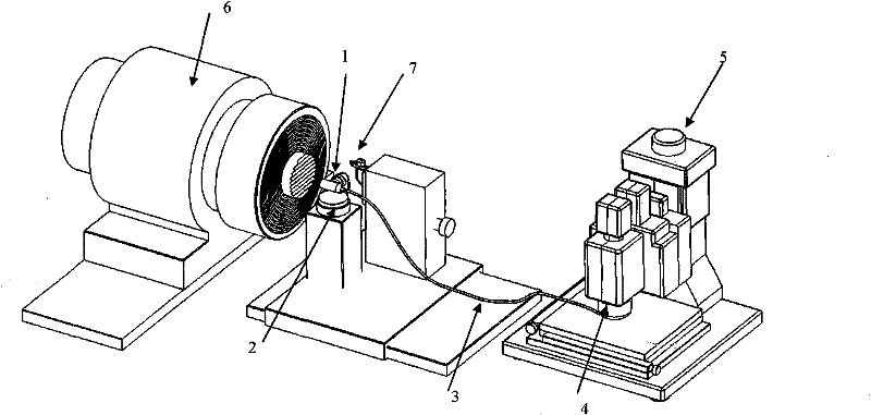
[0025] The invention proposes a flexible measuring head that can be directly placed on an ultra-precision machining machine tool to realize in-situ measurement of a large curvature surface. The measuring device equipped with this flexible measuring head includes: flexible measuring head, image transmission fiber, coupling mirror, optical three-dimensional measuring system, and high-precision turntable. The structure of its in situ measurement application is as follows figure 1 shown.

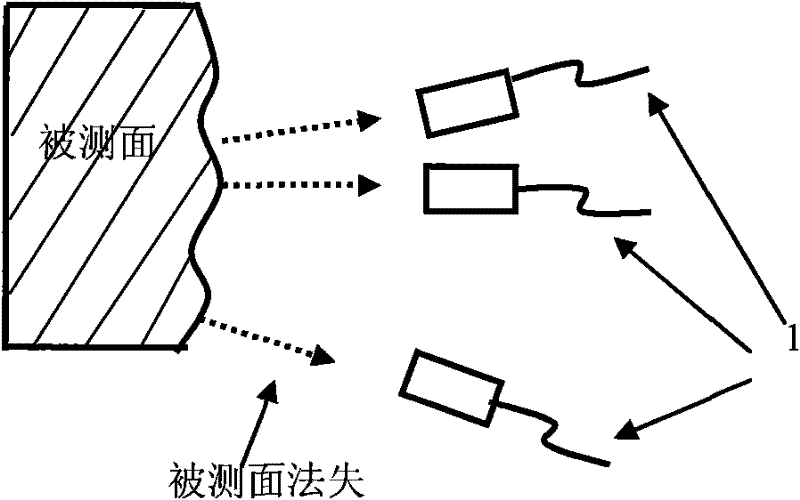
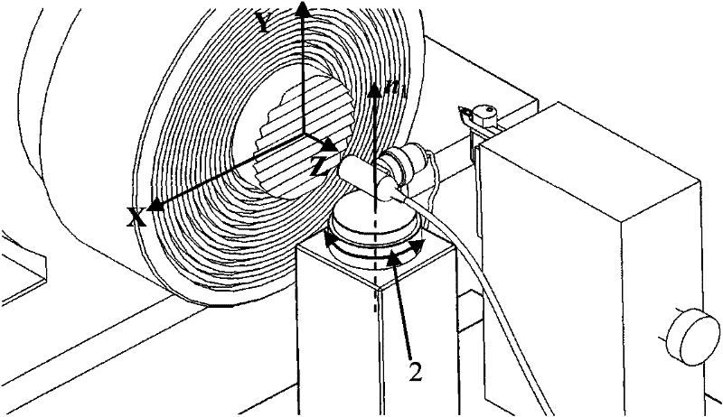
[0026] The optical measurement part of the probe is connected to the image transmission fiber by means of a coupling mirror, and the measured image is collected through the objective lens at the other end. The light can transmit the required light source illumination to the surface of the object to be measured, and at the same time transmit the measurement image modulat...


PUM


Abstract

The invention belongs to the technical field of optical measurement and processing and relates to an ultra-precision in-situ measurement device based on a flexible probe. The ultra-precision in-situ measurement device comprises the flexible probe, image transfer optical fibers, a coupling lens, a high precision rotary table and an optical three-dimensional measurement system, wherein the flexible probe is arranged on the high precision rotary table, the center of the flexible probe is arranged on the axial line of a rotary shaft of the rotary table, and a tested surface image collected by the flexible probe is transferred to the optical three-dimensional measurement system sequentially passing through the image transfer optical fibers and the coupling lens. The invention also provides an ultra-precision processing method realized by utilizing the measurement device. The measurement device can prolong and shorten the optical measurement system and can realize measurement and ultra-precision processing compensation of a large curvature surface shape.

Description

technical field [0001] The invention belongs to the technical field of optical measurement and processing, and relates to an in-situ ultra-precision measuring device suitable for ultra-precision machining machine tools. Background technique [0002] Ultra-precision machining of nanometer-scale complex surfaces is the frontier of advanced manufacturing technology and one of the core supporting technologies for the manufacture of key parts of modern high-tech products. The application in the field is more and more extensive, which greatly improves the processing efficiency of key devices, and becomes the embodiment of the comprehensive strength of a country's national economy, national defense and science and technology. At present, various application fields have gradually put forward higher requirements for the machining accuracy of nano-scale complex curved surfaces. Therefore, the manufacture of high-precision nano-scale complex curved surfaces is the main task in the fiel...

Claims


Application Information

Patent Timeline
Patent Type & Authority Patents(China)
IPC IPC(8): B23Q17/24
Inventor 张效栋房丰洲程颖
Owner TIANJIN UNIV
Learn More