Symmetrically-arranged closed gear transmission system

A technology of gear transmission and symmetrical arrangement, which is applied in the direction of gear transmission, transmission, transmission parts, etc., can solve the problems of unstable center of gravity, easy to sway, unsafe use, etc., and achieve stable center of gravity, not easy to sway, The effect of improving safety

Inactive Publication Date: 2017-02-01
HENGYANG ZHONGDI EQUIP PROSPECTING ENG MACHINERY
View PDF7 Cites 5 Cited by
  • Summary
  • Abstract
  • Description
  • Claims
  • Application Information

AI Technical Summary

Problems solved by technology

It solves the problem of unstable center of gravity, easy swing and unsafe use of the existing gear transmission system during suspended construction work

Method used


Image

  • Symmetrically-arranged closed gear transmission system
  • Symmetrically-arranged closed gear transmission system
  • Symmetrically-arranged closed gear transmission system

Examples


Embodiment 1

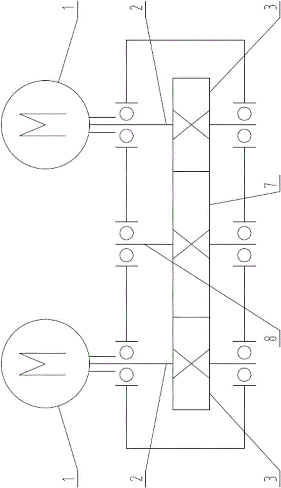
[0016] like image 3 As shown, a symmetrically arranged closed gear transmission system includes a power source 1, an input shaft 2, an input gear 3, an output gear 7, and an output shaft 8. The power source 1 is connected to the input shaft 2, and the input gear 3 On the shaft 2, the output gear 7 is on the output shaft 8 and is externally meshed with the input gear 3. The gear transmission system is symmetrical along the output shaft 8, and the two power sources 1 have the same power, the same rotation direction and output power synchronously. When working, the two power sources 1 output power, through the input shaft 2 and input gear 3 on both sides, the power is transmitted to the corresponding output gear 7 for speed change, and finally the output shaft 8 outputs the power of the speed change. At this time, the output speed is the same as that of the power source The speed difference is small.

Embodiment 2

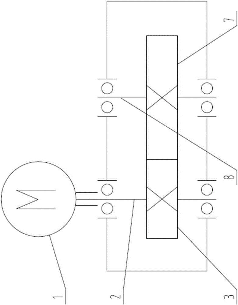
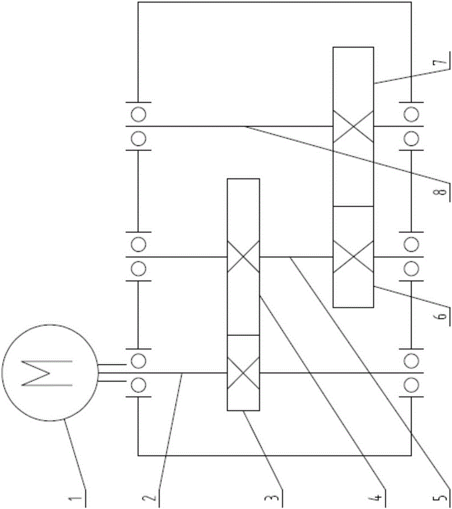
[0018] like Figure 4 As shown, a symmetrically arranged closed gear transmission system includes a power source 1, an input shaft 2, an input gear 3, a transmission gear A4, a transmission shaft 5, a transmission gear B6, an output gear 7 and an output shaft 8; the power source 1 is connected to the input shaft 2, the input gear 3 is on the input shaft 2, the speed change gear A4 and the speed change gear B6 are connected in series on the speed change shaft 5, and the output gear 7 is on the output shaft 8; the input gear 3 is externally meshed with the speed change gear A4 , the transmission gear B6 is externally meshed with the output gear 7; the gear transmission system is symmetrical along the output shaft 8, and the two power sources 1 have the same power, the same rotation direction and synchronous output power. When working, the two power sources 1 output power, and the power is transmitted to the corresponding speed change gear A4 through the input shaft 2 and the inp...

Embodiment 3

[0020] A symmetrically arranged closed gear transmission system, including a power source 1, an input shaft 2, an input gear 3, a transmission gear A4, a transmission shaft 5, a transmission gear B6, a transmission gear C, a transmission shaft, a transmission gear D, an output gear 7 and Output shaft 8; the power source 1 is connected to the input shaft 2, the input gear 3 is on the input shaft 2, the speed change gear A4 and the speed change gear B6 are connected in series on the speed change shaft 5, and the speed change gear C and the speed change gear D are connected in series on the speed change shaft , the output gear 7 is on the output shaft 8; the input gear 3 is externally meshed with the speed change gear A4, the speed change gear B6 is externally meshed with the speed change gear C, and the speed change gear D is externally meshed with the output gear 7; the gear transmission system is along the output shaft 8-axis symmetry, the two power sources 1 have the same powe...


PUM


Abstract

A symmetrically-arranged closed gear transmission system comprises power sources, input shafts, input gears, an output gear and an output shaft. Each power source is connected with the corresponding input shaft; each input gear is on the corresponding input shaft; and the output gear is located on the output shaft and externally engaged with the input gears. The gear transmission system is in axis symmetry along the output shaft, and the two power sources are the same in power and rotating direction and output power synchronously. According to the symmetrically-arranged closed gear transmission system, by the adoption of the technical scheme, compared to the prior art, a fully-mirror-symmetrical closed structure is adopted, so that in construction, the system is kept stable in the center of gravity, is not prone to swinging, and is suitable for construction operation in a suspended mode and a vertical movement mode; and the safety and stability of the system are improved, and the using range is extended.

Description

technical field [0001] The invention relates to a gear transmission system, in particular to a symmetrically arranged closed gear transmission system. Background technique [0002] In the field of mechanical transmission, gear transmission is the most commonly used power transmission system. Ordinary gear transmission system (see attached figure 1 ) is to use the power source 1 to output power, and transmit the power to the output gear 7 through the input shaft 2 and the input gear 3, and finally the output shaft 8 will output the shifted power; when the required output speed and the speed of the power source differ greatly , then add speed change gear A4, speed change shaft 5 and speed change gear B6 (see attached figure 2 ), at this time, the power source 1 outputs power, and the power is transmitted to the transmission gear A4 through the input shaft 2 and the input gear 3, and then transmitted to the output gear 7 through the transmission shaft 5 and the transmission g...

Claims


Application Information

Patent Timeline
Patent Type & Authority Applications(China)
IPC IPC(8): F16H1/22F16H57/023
CPCF16H1/22F16H57/023
Inventor 欧阳志强沈博志刘跃进
Owner HENGYANG ZHONGDI EQUIP PROSPECTING ENG MACHINERY
Why Eureka
Try Eureka