Long linear array push-broom infrared thermal imaging system based on inclined special-shaped cold shield

An infrared thermal imaging and special-shaped technology, which is applied in the direction of measuring devices, instruments, scientific instruments, etc., can solve the problems of reducing the optical efficiency of the infrared imaging system, incomplete matching, and system complexity, and achieves small size, simple processing and adjustment, The effect of high sensitivity

Active Publication Date: 2017-02-01
SHANGHAI INST OF TECHNICAL PHYSICS - CHINESE ACAD OF SCI
View PDF6 Cites 2 Cited by
  • Summary
  • Abstract
  • Description
  • Claims
  • Application Information

AI Technical Summary

Benefits of technology

The technology described by this patented solution allows an object being detected (the target) to have two images - one on top of another – that match up well when viewed from different angles or directions respectively. This makes possible precise measurements over longer distances without relying solely upon multiple cameras. It also includes features like secondary imagery and positioned behind the camera's line of sight, making them ideal for detecting objects at short range. Overall, these improvements make the device more efficient than previous methods while still providing accurate results even under challenging conditions such as low temperatures during flight operations.

Problems solved by technology

The technical problem addressed by this patented technology relates to improving upon traditional methods used during manufacturing or assembly processes such as cooling an object with liquid nitrogen (LN2) before mounting it into another structure like a spectrometer housing. These techniques have limitations due to factors including temperature differences caused by different materials being processed at high temperatures, difficulty achieving proper alignment between the device itself and other structures while also reducing its size without adding extra parts.

Method used


Image

  • Long linear array push-broom infrared thermal imaging system based on inclined special-shaped cold shield
  • Long linear array push-broom infrared thermal imaging system based on inclined special-shaped cold shield
  • Long linear array push-broom infrared thermal imaging system based on inclined special-shaped cold shield

Examples


Embodiment Construction

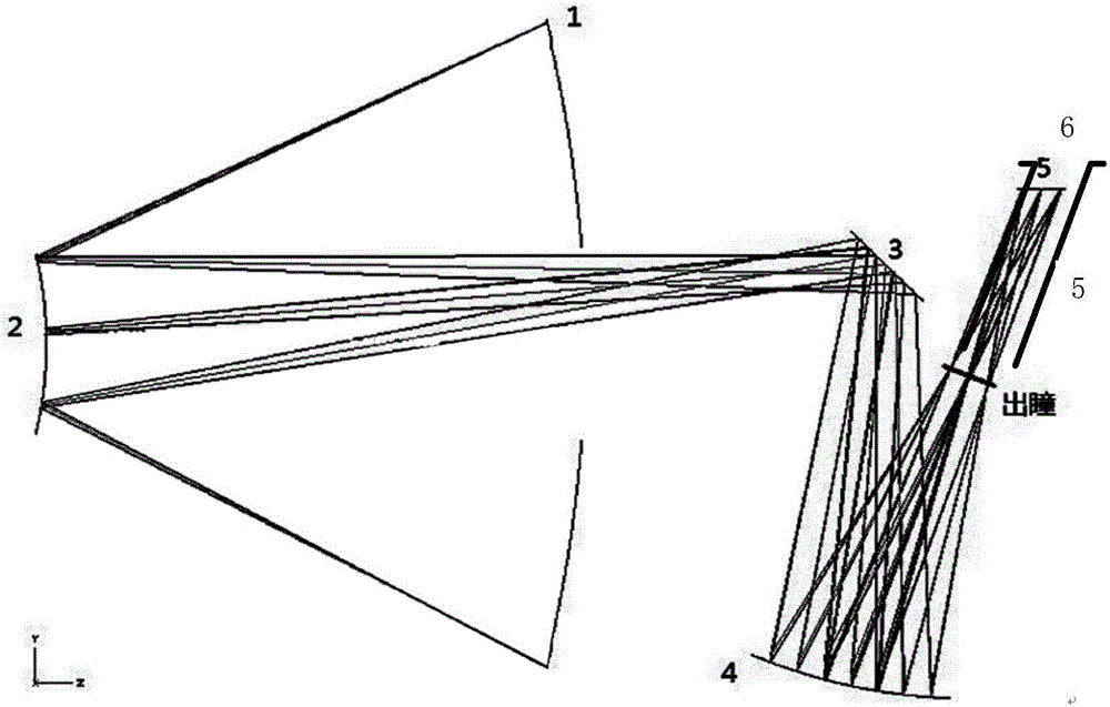
[0021] According to the invention figure 1 Based on the optical system structure shown in , we have designed a high-sensitivity long linear array push-broom infrared thermal imaging system, and its technical indicators are as follows:

[0022]

[0023] The specific structural parameters are as follows:

[0024] element Off-axis amount / mm Radius of curvature / mm Interval / mm primary mirror 1 / 420.339 d1=162.879 secondary mirror 2 / 119.328 / Plane Mirror 3 d3=24.042 / d2=91.11 Three mirrors 4 d4=110 158.934 d5=9.958 Detector 5 d7=47.957 / d6=46.042

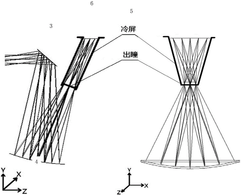
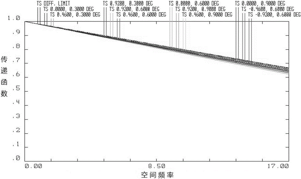
[0025] The inclined special-shaped cold screen of the system is fully matched with the exit pupil, as shown in the attached figure 2 As shown, the image quality of the optical system is good, and the optical modulation transfer function is shown in the attached image 3 shown.


PUM


Abstract

The invention discloses a long linear array push-broom infrared thermal imaging system based on an inclined special-shaped cold shield, which is composed of a primary mirror, a secondary mirror, a turning focusing mirror, a tertiary mirror, a mechanical structure, a long linear array infrared focal plane, the inclined special-shaped cold shield and a linear array infrared focal plane detector. Light beams from a target sequentially pass through the primary mirror, the secondary mirror, the turning focusing mirror, and the tertiary mirror and are finally imaged on the linear array infrared focal plane detector. The exit pupil of an optical system is located before the linear array infrared focal plane detector, which is perfectly matched with the inclined special-shaped cold shield and realizes 100% cold stop. The system is compact in structure, light in weight, small in size, simple in processing and debugging, and can be used for high-sensitivity infrared thermal imaging detector, and is particularly suitable for aerospace large-caliber high-resolution infrared thermal imaging application.

Description


Claims


Application Information

Patent Timeline
Owner SHANGHAI INST OF TECHNICAL PHYSICS - CHINESE ACAD OF SCI
Why Eureka
Try Eureka