Supercharge Your Innovation With Domain-Expert AI Agents!

Stamping die and wire terminal crimping machine using the die

A stamping die and frame technology, applied in the field of wire terminal crimping machine, can solve the problems of low efficiency, high processing waste rate, low work efficiency, etc., and achieve the effect of automatic positioning, high product quality and high production efficiency

Active Publication Date: 2018-11-09
CHANGSHA JINGHUA ELECTRONICS TECH
View PDF5 Cites 0 Cited by
  • Summary
  • Abstract
  • Description
  • Claims
  • Application Information

AI Technical Summary

Problems solved by technology

[0002] Existing stamping machines often use manual or semi-manual operation, which makes it difficult to realize automatic material feeding and low work efficiency; due to the need for manual participation, the safety is poor; due to the long-term work of the operator, it is difficult to concentrate for a long time, and the processing waste rate High, causing a lot of material waste
[0003] Especially in the field of wire terminal crimping machines, there is still a lack of such equipment for automatic feeding and quick connection and fixing of cables and buckles
In the traditional wire terminal crimping process, it is first necessary to cut off the buckles on the continuous buckles, collect them, manually connect the cables to the buckles, and then send them to the mold of the crimping machine, manually position them, and then operate the crimping machine For crimping, the work is cumbersome, the efficiency is low, the safety is poor, the yield rate is low, and the waste is serious

Method used


Image

  • Stamping die and wire terminal crimping machine using the die
  • Stamping die and wire terminal crimping machine using the die

Examples


Embodiment Construction

[0022] It should be noted that, in the case of no conflict, the embodiments of the present invention and the features in the embodiments can be combined with each other. The present invention will be described in detail below with reference to the accompanying drawings and examples.

[0023] Combine below figure 1 and figure 2 , the preferred embodiments of the present invention will be described in further detail.

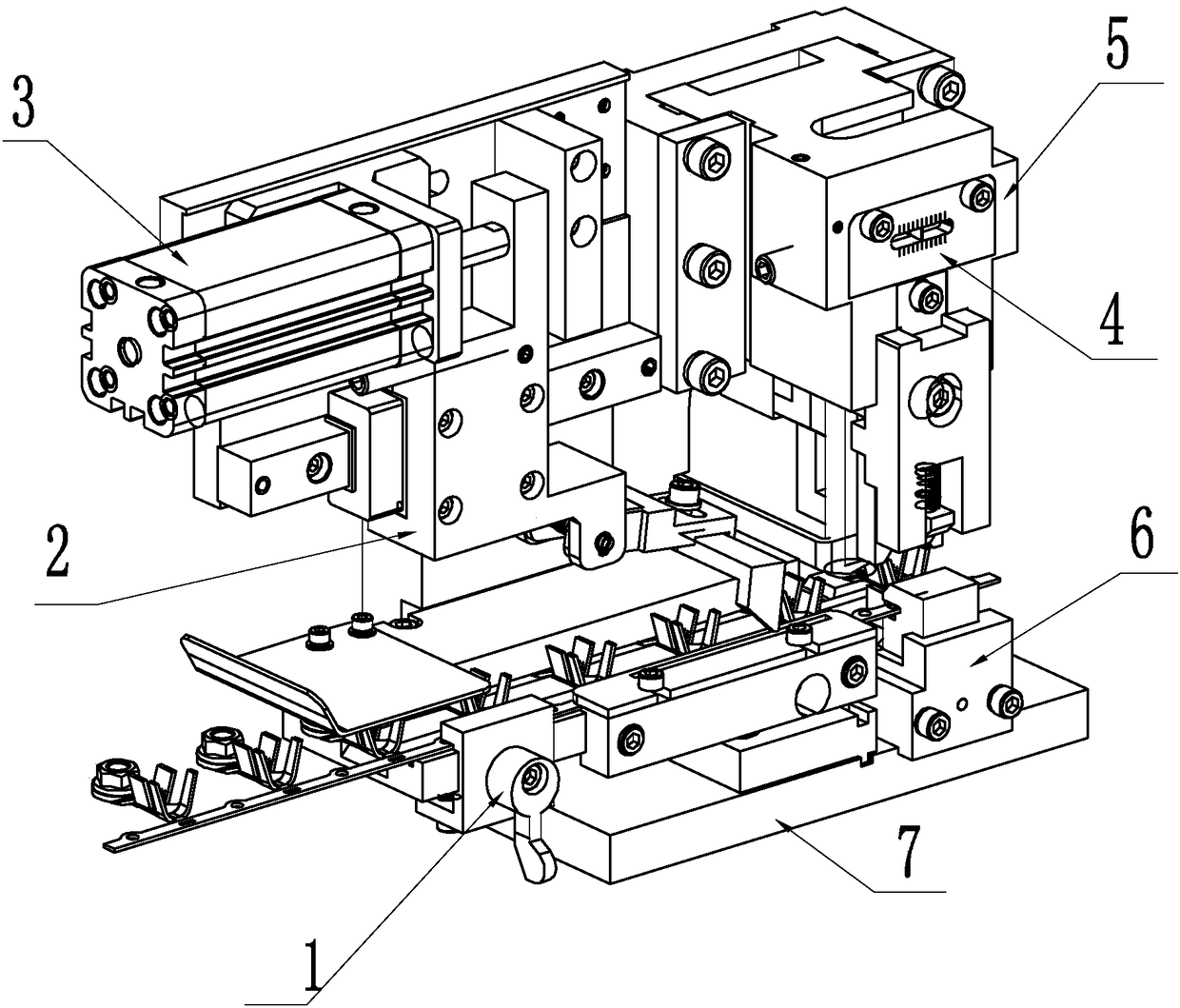
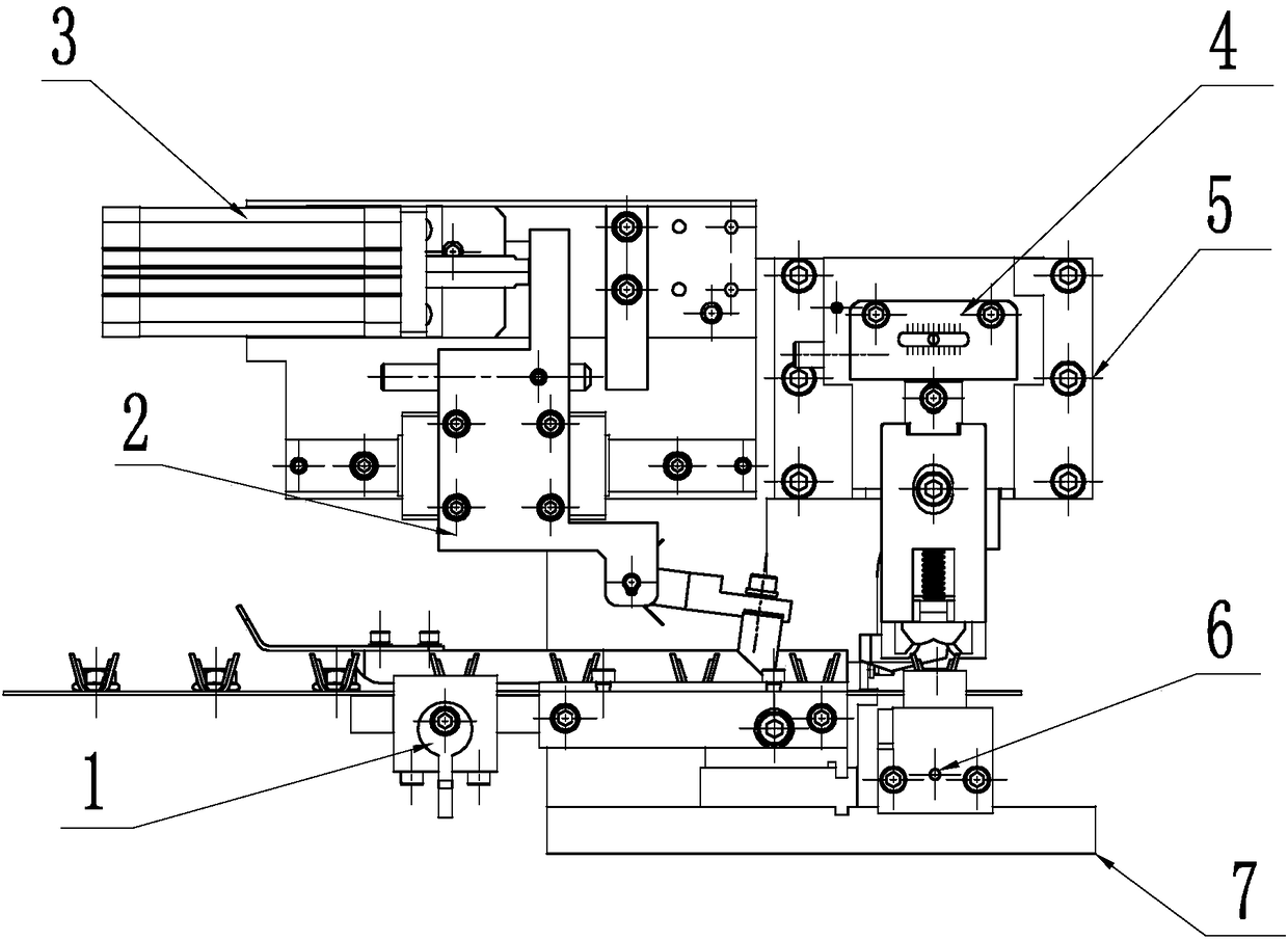
[0024] This embodiment provides a stamping die for automatic feeding, including a lower die fixed on the frame 7, an upper die connected to the output shaft of the stamping cylinder, a limit module for limiting the continuous buckle, and a die fixed on the machine frame. On the frame 7, push the feeding module that moves continuously with buckles.

[0025] In the production process of the existing wire terminal buckle products, in fact, all the buckles will be fixed on a continuous fixed metal wire after being formed. The metal wire is provided with holes to f...


PUM


Abstract

The invention discloses a stamping die and a wire terminal crimping machine using the same. The stamping die comprises a lower die fixed on a frame and an upper die connected with the output shaft of a stamping cylinder, and the lower die and the upper die work together to implement stamping. The lower die comprises a lower blade sub-package fixed on the frame and a blade fixed on the lower blade sub-package. The upper die comprises a guide mechanism fixed on the frame, and a slider pressure head mechanism fixed on the guide mechanism and connected with the output shaft of the stamping cylinder. Automatic positioning and feeding can be realized. Work is smooth. The production efficiency is high. The product quality is higher.

Description

technical field [0001] The invention belongs to the technical field of mechanical processing equipment, and relates to a mold structure and an electric wire terminal crimping machine using the mold. Background technique [0002] Existing stamping machines often use manual or semi-manual operation, which makes it difficult to realize automatic material feeding and low work efficiency; due to the need for manual participation, the safety is poor; due to the long-term work of the operator, it is difficult to concentrate for a long time, and the processing waste rate High, resulting in a lot of material waste. [0003] Especially in the field of wire terminal crimping machines, there is still a lack of such equipment for automatic feeding and fast connection and fixing of cables and buckles. In the traditional wire terminal crimping process, it is first necessary to cut off the buckles on the continuous buckles, collect them, manually connect the cables to the buckles, and then...

Claims


Application Information

Patent Timeline
Patent Type & Authority Patents(China)
IPC IPC(8): H01R43/048H01R43/052
CPCH01R43/048H01R43/052
Inventor 邓晓红罗朝辉
Owner CHANGSHA JINGHUA ELECTRONICS TECH
Features
  • R&D
  • Intellectual Property
  • Life Sciences
  • Materials
  • Tech Scout
  • Unparalleled Data Quality
  • Higher Quality Content
  • 60% Fewer Hallucinations
Learn More