Method for automatically positioning main shaft during roller exchange of finishing mill

An automatic positioning and finishing mill technology, applied in the direction of metal rolling stands, metal rolling mill stands, metal rolling, etc., can solve the problems of poor cooling of steel plate shape, low average cooling rate, insufficient and other problems, and achieves improved replacement. Roller operation efficiency, realization of positioning, and the effect of automatic and precise positioning

Active Publication Date: 2012-05-23
BAOSHAN IRON & STEEL CO LTD
View PDF5 Cites 18 Cited by
  • Summary
  • Abstract
  • Description
  • Claims
  • Application Information

AI Technical Summary

Problems solved by technology

[0008] In view of the above-mentioned shortcomings of low average cooling rate, poor steel plate shape and insufficient cooling in the prior art, the purpose of the present invention is to provide a method for automatic positioning of the main drive shaft of a finishing mill, which is simple and convenient to operate. Fast and full cooling

Method used


Image

  • Method for automatically positioning main shaft during roller exchange of finishing mill
  • Method for automatically positioning main shaft during roller exchange of finishing mill
  • Method for automatically positioning main shaft during roller exchange of finishing mill

Examples


Embodiment Construction

[0029] The technical solutions of the present invention will be further described below in conjunction with the accompanying drawings and embodiments.

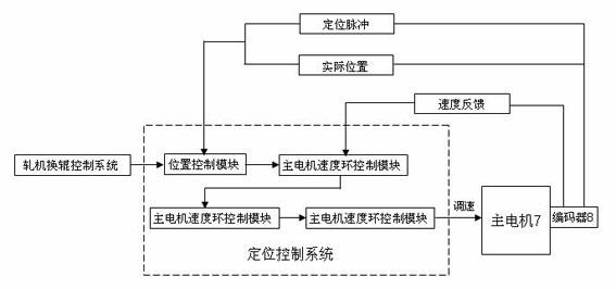
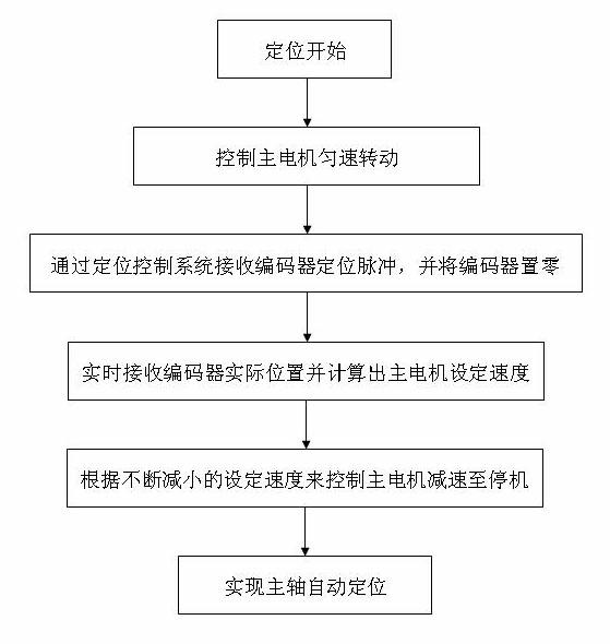
[0030] see figure 2 , image 3 As shown, the automatic positioning method of the main transmission shaft of the finishing mill of the present invention specifically includes the following steps:

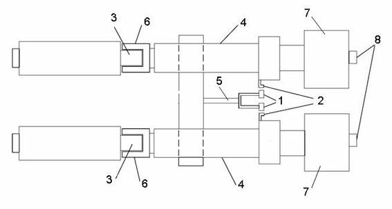
[0031] A. When the rolling mill enters the roll change program and proceeds to the main shaft positioning step, the operator operates the panel of the rolling mill roll change control system on the site to issue a positioning command, and controls the main motor of the main shaft to drive the main shaft to rotate at a constant speed of 0.5m / s.

[0032] B. Utilize the encoder 8 that rolling mill main motor 7 carries (see figure 1 , figure 2 ), use the zero pulse sent by the encoder as the positioning pulse, and set the position of the encoder to zero when the position control module of the positioning control system receives th...


PUM


Abstract

The invention discloses a method for automatically positioning a main transmission shaft of a finishing mill. In the method, the control speed of a main motor is calculated by using a zero position pulse of an encoder of the main motor as a positioning pulse through the difference between an actual rotation position and a target rotation position of the encoder, so that the main motor is controlled in a deceleration manner to automatically position the main shaft; therefore, the main shaft can be automatically and accurately positioned, and the improvement on roller exchange operation efficiency of the finishing mill is facilitated.

Description

[0001] technical field [0002] The invention relates to the roll changing technology of a finishing mill, and more specifically relates to an automatic positioning method for a main transmission shaft of a finishing mill. [0003] Background technique [0004] The number of work roll changes in the finishing mills of heavy plate enterprises has gradually increased with the increase in production capacity, and has been shortened from once every five days to about two and a half days, and the average roll change time has been shortened from the initial 1 hour to the current 25 hours. minutes or so. It can be said that the level of work roll change has been greatly improved, which has made a great contribution to the increase in production capacity. The main transmission shaft of the finishing mill (hereinafter referred to as the main shaft) is connected to the work rolls in a structure in which the flat head and the flat head cover are nested with each other. When the old ...

Claims


Application Information

Patent Timeline
Patent Type & Authority Applications(China)
IPC IPC(8): B21B31/08
Inventor 顾华仲鉴丁海绍汪鎏毛卫山张栋戎戈
Owner BAOSHAN IRON & STEEL CO LTD
Why Eureka
Try Eureka