Magnetic steel assembling equipment and magnetic steel assembling method therefor

A magnetic steel and equipment technology, applied in electromechanical devices, manufacturing motor generators, manufacturing stator/rotor bodies, etc., can solve the problems of mechanical positioning wear, magnetic steel falling off positioning accuracy, and insufficient magnetization intensity, etc., to reduce The effect of contact error, ensuring accuracy and assembly efficiency, improving production flexibility and use efficiency

Active Publication Date: 2017-02-01
NINGBO SUNNY INTELLIGENT TECH CO LTD
View PDF10 Cites 12 Cited by
  • Summary
  • Abstract
  • Description
  • Claims
  • Application Information

AI Technical Summary

Problems solved by technology

[0004] CN105846615A provides an automatic equipment scheme for overall magnetization after assembly. Although the overall magnetization process is relatively low in assembly difficulty, it has problems such as narrow adaptability, huge loss when there are defective products in magnetization, and insufficient magnetization intensity.
The mechanical positioning is also easy to be worn out in the production process, and must be overhauled frequently; this invention has very high requirements on the dimensional accuracy of the magnet steel and the iron core and the positioning accuracy of the positioning mechanism, and it is difficult to guarantee both in actual production. meet the requirements
[0006] A magnet assembly machine described in CN102611258A provides a scheme in which multiple groups of magnets are simultaneously pushed in, which greatly improves efficiency. Its feeding system is relatively close to that of CN105553197A, and profiling plastic damping is added to the push-in system The mechanism can control the speed and strength of the magnetic steel pushing in, and has a certain enhancement to the positioning accuracy of the magnetic steel when pushing in, but there is still the problem in CN105553197A that the magnetic steel will be damaged during the feeding and pushing process
At the same time, the above-mentioned two patents of CN105553197A and CN102611258A only involve the process of loading the magnetic steel into the iron core, and have not completed the complete assembly of the magnetic steel assembly. In the process of material circulation, there are problems such as magnetic steel falling off and positioning accuracy.

Method used


Image

  • Magnetic steel assembling equipment and magnetic steel assembling method therefor
  • Magnetic steel assembling equipment and magnetic steel assembling method therefor
  • Magnetic steel assembling equipment and magnetic steel assembling method therefor

Examples


Embodiment approach

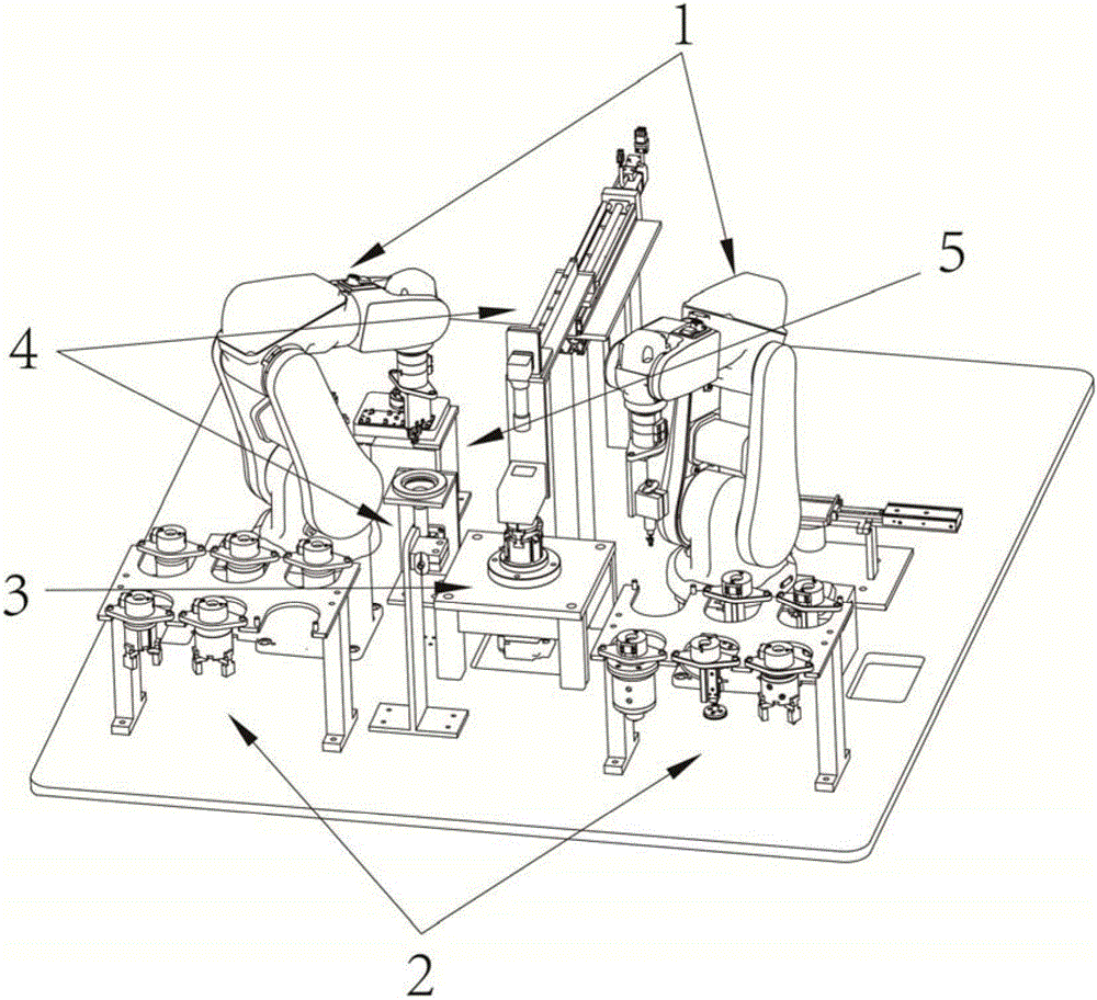
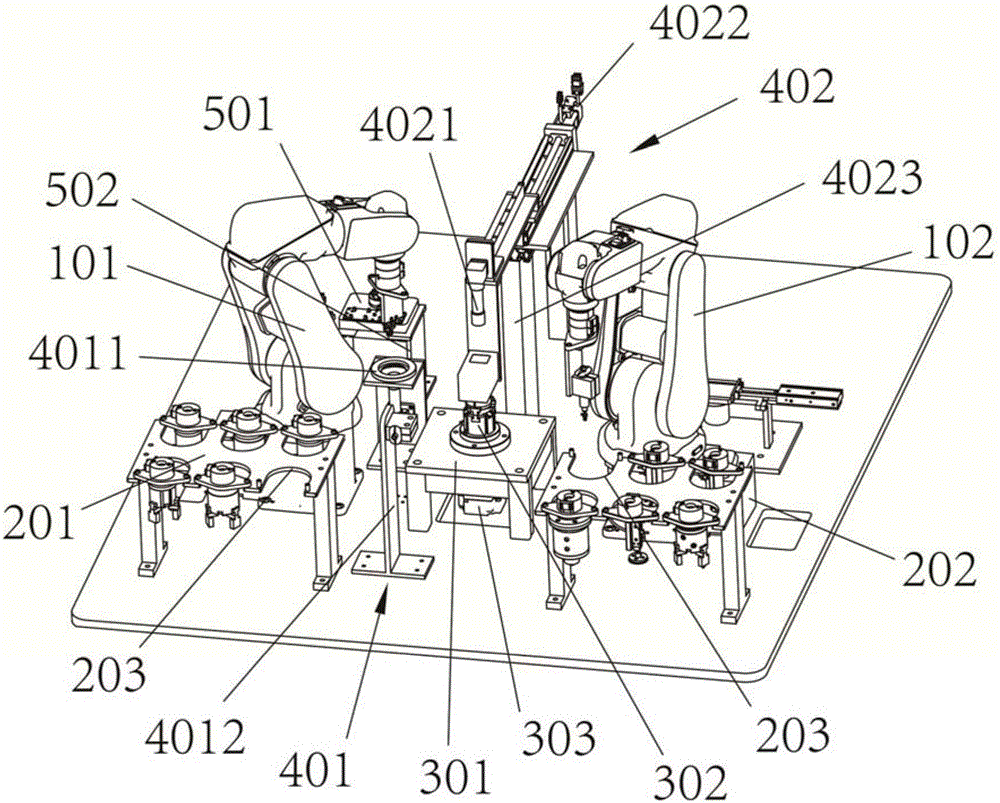
[0053] Such as figure 2 As shown, according to an embodiment of the present invention, the tooling unit 2 includes a clamping tooling platform 201 and a fastening tooling platform 202 . As shown in the figure, in this embodiment, the clamping tool table 201 is adjacent to the clamping mechanism 101 and is located on the same side in the longitudinal direction in the figure, that is, the left side in the figure. As shown in the figure, the clamping tool table 201 and the clamping mechanism 101 are located on one side of the assembly unit 3 . The fastening tool table 202 and the fastening mechanism 102 are arranged at intervals corresponding to each other, and are located on the same side of the longitudinal direction in the figure together with the fastening mechanism 102 , that is, the right side as shown in the figure. As shown in the figure, in this embodiment, the clamping tool table 201 and the fastening tool table 202 are located on the same side of the transverse centr...


PUM


Abstract

The invention relates to magnetic steel assembling equipment. The magnetic steel assembling equipment comprises an execution unit, a tool unit, an assembling unit and a detecting-positioning unit, wherein the detecting-positioning unit comprises a magnetic steel detecting-positioning mechanism for detecting position information of the magnetic steel and an iron core detecting-positioning mechanism for detecting position information of an iron core. By adoption of the equipment, quick and high-precision assembling of the magnetic steel can be realized; and in addition, detecting-positioning is performed in assembling of the magnetic steel in each time, so that positioning accuracy is ensured.

Description

technical field [0001] The invention relates to a device for assembling magnet steel and a method for assembling magnet steel. Background technique [0002] Chinese patent 201210117853.4 discloses a magnetic steel automatic assembly machine. This device uses the feeding mechanism to provide the magnetic steel to the motor rotor, the rotary positioning mechanism locates the magnetic steel rotor that needs to be installed, the servo motor is connected to the turntable, first the position of the motor rotor magnetic steel groove is detected by the camera of the visual inspection device, and the control system Control the rotation of the servo motor to align the magnetic steel groove with the magnetic steel guide groove, and then the servo motor can control the rotation angle under the control of the control system to meet the position requirements of the magnetic steel. The overall structure of this device is arranged from top to bottom, the structure is complex, and the longi...

Claims


Application Information

Patent Timeline
Patent Type & Authority Applications(China)
IPC IPC(8): H02K15/03
CPCH02K15/03
Inventor 陈腾翁九星刘飞杨赛女赵姝炜
Owner NINGBO SUNNY INTELLIGENT TECH CO LTD
Why Eureka
Try Eureka