I/O port circuit structure with hot plug function

A port circuit, hot-swap technology, applied in logic circuits, logic circuit coupling/interface using field effect transistors, logic circuit connection/interface layout, etc., can solve the problems of system voltage drop, system large, system capacitor discharge and so on

Active Publication Date: 2017-02-01
58TH RES INST OF CETC
View PDF3 Cites 9 Cited by
  • Summary
  • Abstract
  • Description
  • Claims
  • Application Information

AI Technical Summary

Problems solved by technology

The inflow current creates a large demand on the system, which may cause the system capacitor to discharge and the system voltage to drop

Method used


Image

  • I/O port circuit structure with hot plug function
  • I/O port circuit structure with hot plug function
  • I/O port circuit structure with hot plug function

Examples


Embodiment Construction

[0020] Below in conjunction with accompanying drawing, technical scheme of the present invention is described in further detail:

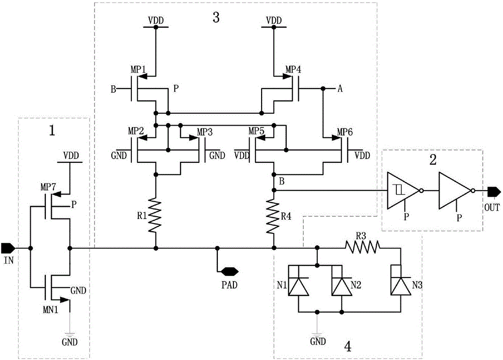
[0021] Such as figure 1 As shown, an I / O port circuit structure with hot swap function includes four main modules, namely an output buffer module 1 , an input buffer module 2 , a hot swap module 3 , and an ESD protection module 4 . The output buffer module 1 is connected to the PAD terminal, the input signal, and the input and output selection control terminal, and is used to realize the function of the port PAD as the output terminal; the input buffer module 2 is connected to the PAD terminal and the output signal, and is used to realize the function of the port PAD as the input terminal; The pull-out module 3 is connected to the PAD end through a resistor to realize the plug-in function; the ESD protection module 4 is connected to the PAD end to realize the 2000V ESD protection capability.

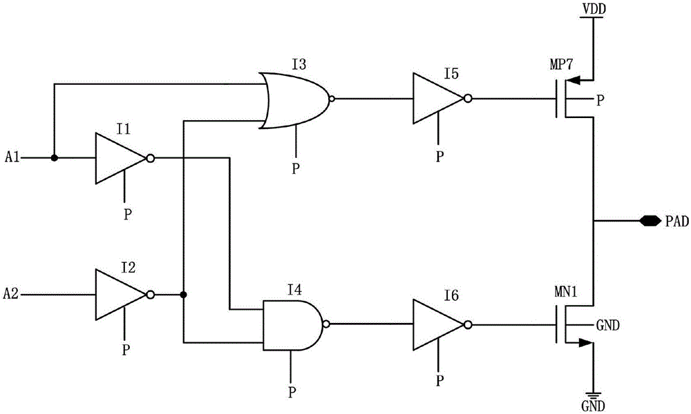
[0022] The output buffer module 1 in this structure is...


PUM


Abstract

The invention relates to an I/O port circuit structure with a hot plug function. The structure comprises an output buffer module, an input buffer module, a hot plug module and an ESD protection module, wherein the output buffer module is connected to a PAD end, an input signal and an input-output selection control end and is used for realizing a function of taking a port PAD as an output end; the input buffer module is connected to the PAD end and an output signal and is used for realizing a function of taking the port PAD as an input end; the hot plug module is connected to the PAD end through a resistor and is used for realizing hot plug; and the ESD protection module is connected to the PAD end and is used for realizing ESD protection of 2000 V. Through adding the hot plug circuit structure based on the conventional I/O port structure, the hot plug function of the device port is realized; and furthermore, the hot plug function is guaranteed while the structure has ESD resistance of 2000 V.

Description

technical field [0001] The invention relates to a hot plug circuit structure, in particular to an I / O port circuit structure with a hot plug function. Background technique [0002] Hot-swapping represents the ability of a system to load or remove power while the input, output, and signal bus are all in working condition. Hot plugging can be used to control unpowered circuit boards to power on and manage system responses, so that the motherboard and plug-in cards are not damaged. [0003] When the circuit board is connected to a live system, since the board is inserted into the connector by shaking, the connection between the board and the power supply will be broken many times. It takes a few milliseconds for the board and connector to fully mate. When the board is inserted, the capacitors on the board begin to charge, drawing current from the live system. When the capacitors are initially charged, the board behaves as a short circuit and immediately draws a large amount ...

Claims


Application Information

Patent Timeline
Patent Type & Authority Applications(China)
IPC IPC(8): H03K19/0185
CPCH03K19/018507
Inventor 印琴朱晓宇于宗光蔡洁明徐睿
Owner 58TH RES INST OF CETC
Why Eureka
Try Eureka