Adjustable foot-shaped scanner

一种扫描仪、可调节的技术,应用在脚或鞋楦的测量装置、医药科学、服饰等方向,能够解决不能获取三维数据、不能体现脚部变形、不能满足数据需求等问题,达到可靠数据参考、便于开发设计和制作的效果

Active Publication Date: 2017-02-08
郑士超
View PDF6 Cites 3 Cited by
  • Summary
  • Abstract
  • Description
  • Claims
  • Application Information

AI Technical Summary

Problems solved by technology

[0003] But the foot three-dimensional scanner in the prior art has the following disadvantages: 1, the foot three-dimensional scanner that cannot bear the weight can only utilize the three-dimensional scanner to scan under the situation that people's feet are suspended in the air, and the foot shape taken 3D data cannot reflect the deformation of the foot when a person stands and bears weight; 2. A load-bearing 3D scanner for the foot usually requires the person to stand horizontally on a platform, and then obtain the 3D data of the foot shape through the 3D scanner. The obtained 3D data of the foot shape can only reflect the shape of the foot when the foot is standing horizontally, and cannot obtain the 3D data of the foot shape under the condition that the foot bears weight and the heel has a certain height
[0004] The above two shortcomings are very useful in the fields of footwear design, development and processing, personalized foot measurement, shoe last development and design, medical foot shape correction, ergonomic foot shape statistics, and human foot research. The biggest deficiency is that it cannot meet the data requirements of the footwear industry for the foot shape; we know that shoes have different heights, especially women's shoes, from flat shoes to high-heeled shoes with more than ten centimeters. When wearing flat shoes and high-heeled shoes, the foot will undergo great deformation, including when people stand horizontally and exercise, the shape of the foot is also constantly changing. Obviously, simply scan the shape of the foot in a suspended state or when the foot is standing horizontally The data is not enough to meet the actual needs of the footwear industry

Method used


Image

  • Adjustable foot-shaped scanner
  • Adjustable foot-shaped scanner
  • Adjustable foot-shaped scanner

Examples


Embodiment Construction

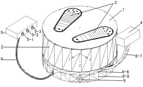
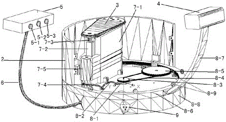
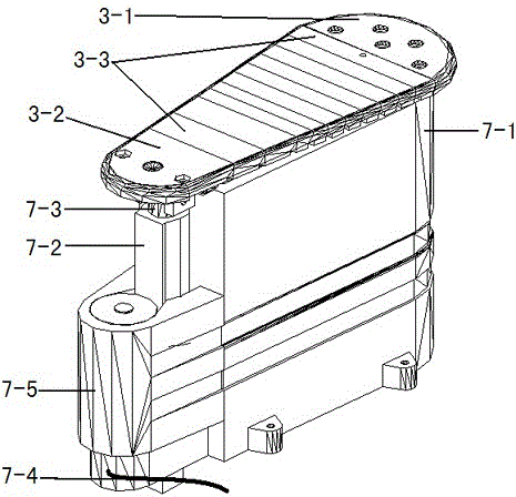
[0031] Refer to attached figure 1, the segmented adjustable three-dimensional foot scanner mentioned in the present invention includes: a housing part, a scanner rotating part, a scanner head, a controller part, the housing part is provided with a segmented foot rest part, and the housing Part of the outer part is connected to the scanner head through the scanner rotating part to rotate and scan the segmented footrest part; the shell part includes cover 1, enclosure 2 and base 8-8, the upper part of enclosure 2 is cover 1, and the lower part It is movably connected with the base 8-8; the cover 1 and the enclosure 2 are connected together through the positioning screws 3-8; the enclosure 2 and the base 8-8 are connected together through the positioning screws 3-8; the foot support 3 is the position where the feet stand; Scanner head 4 is the member of scanning foot shape; Controller 5 is the control system of stepping motor 8-1 and electric push rod 7-2; Data line 6 is to conne...


PUM


Abstract

The invention relates to an adjustable foot-shaped scanner. The technical scheme is that the adjustable foot-shaped scanner comprises a shell part, a scanner rotating part, a scanner machine head and a controller part, wherein the shell part is provided with a sectional foot support part and a heel height adjusting part; the outer side of the shell part is connected with the scanner machine head through the scanner rotating part so as to rotationally scan the sectional foot support part. According to the adjustable foot-shaped scanner disclosed by the invention, foot shapes, especially, deformation generated under the situation that the body weight is borne by feet, in various status can be scanned, so that scanned foot shape data accord more with an actual situation; compared with a common scanner and a foot-shaped scanner which can just stand horizontally, the adjustable foot-shaped scanner has the obvious advantage in respect of obtaining foot shape data; reliable data are provided for subsequently utilizing the foot shape data, convenience is provided for development design and manufacturing of shoemaking industry, and more reliable data reference can be provided for the fields of medical foot shape correction, man-machine engineering foot shape statistics, human body foot research and the like.

Description

technical field [0001] The invention relates to a foot shape scanner, in particular to an adjustable foot shape scanner. Background technique [0002] In many cases, it is necessary to measure the shape of the foot more accurately, such as shoe design, development and processing, customized footwear, shoe last development and design, medical foot shape correction, ergonomic foot shape statistics, human foot research and other fields. In the past, people generally used a tape measure to measure the data of multiple parts of the foot by manual means. The foot shape data measured with a tape measure is not only limited but also has low accuracy. With the development of science and technology, 3D foot scanners are currently used to measure the 3D data of the foot shape. The measured foot shape data is not only accurate but also has higher value for subsequent development and utilization. [0003] But the foot three-dimensional scanner in the prior art has the following disadva...

Claims


Application Information

Patent Timeline
Patent Type & Authority Applications(China)
IPC IPC(8): A43D1/02A61B5/107
CPCA43D1/02A61B5/1074
Inventor 郑士超
Owner 郑士超
Why Eureka
Try Eureka