Plasma auxiliary high-energy planetary ball mill device

A planetary ball milling and plasma technology, applied in grain processing and other directions, can solve problems such as difficult to improve and complex structure, and achieve the effects of accelerated ball milling, uniform energy reception, and fine powder

Active Publication Date: 2010-08-11
SOUTH CHINA UNIV OF TECH
View PDF1 Cites 0 Cited by
  • Summary
  • Abstract
  • Description
  • Claims
  • Application Information

AI Technical Summary

Problems solved by technology

However, since the planetary ball mill needs to realize the rotation and revolution of the ball mill jar, it has the disadvantage of complex structure and is difficult to improve. To introduce the plasma-assisted technology into the planetary ball mill, it is necessary to solve the difficult problems of stable power supply of the ball mill jar electrode, electrode installation, etc.

Method used


Image

  • Plasma auxiliary high-energy planetary ball mill device
  • Plasma auxiliary high-energy planetary ball mill device
  • Plasma auxiliary high-energy planetary ball mill device

Examples


Embodiment 1

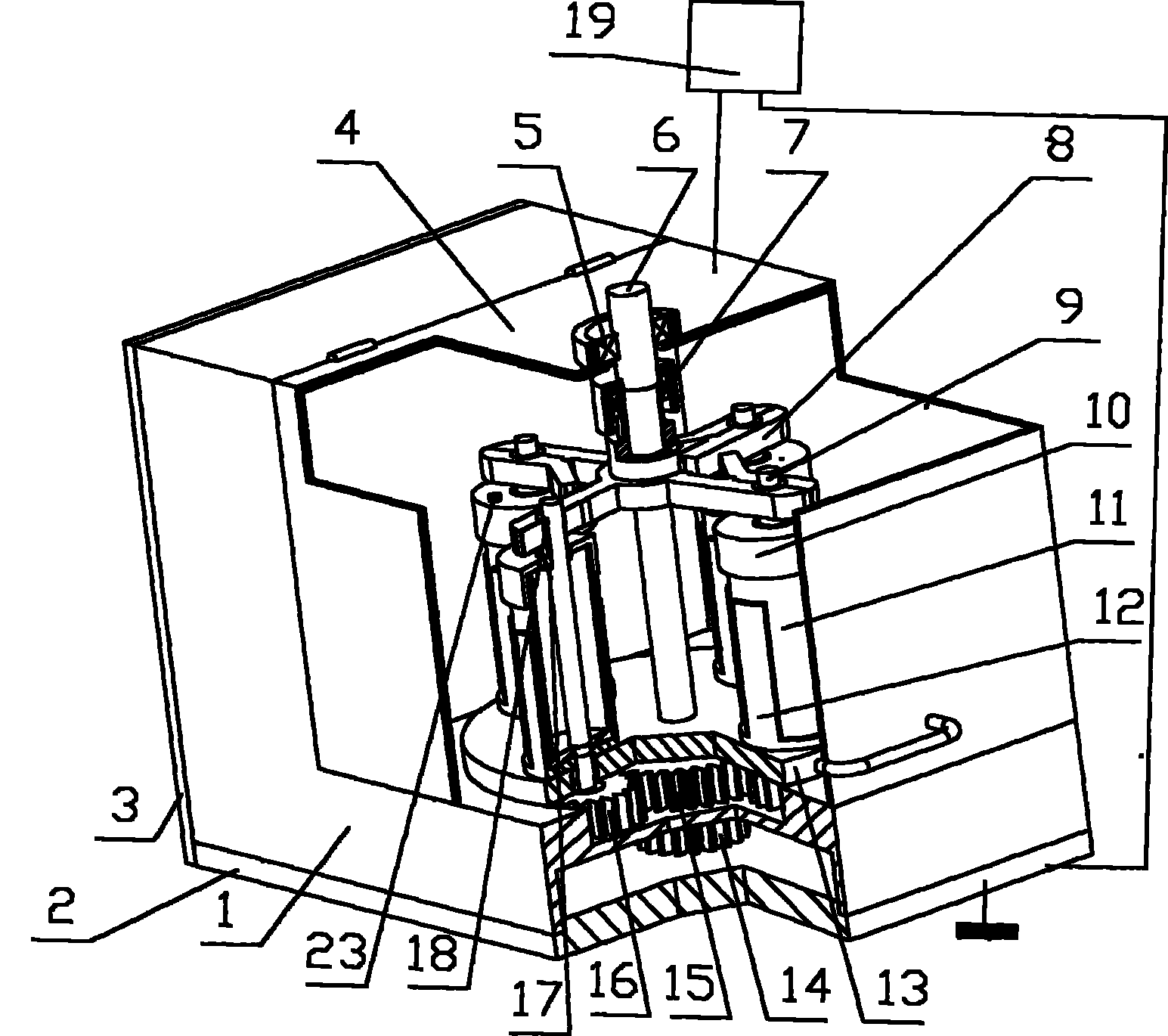
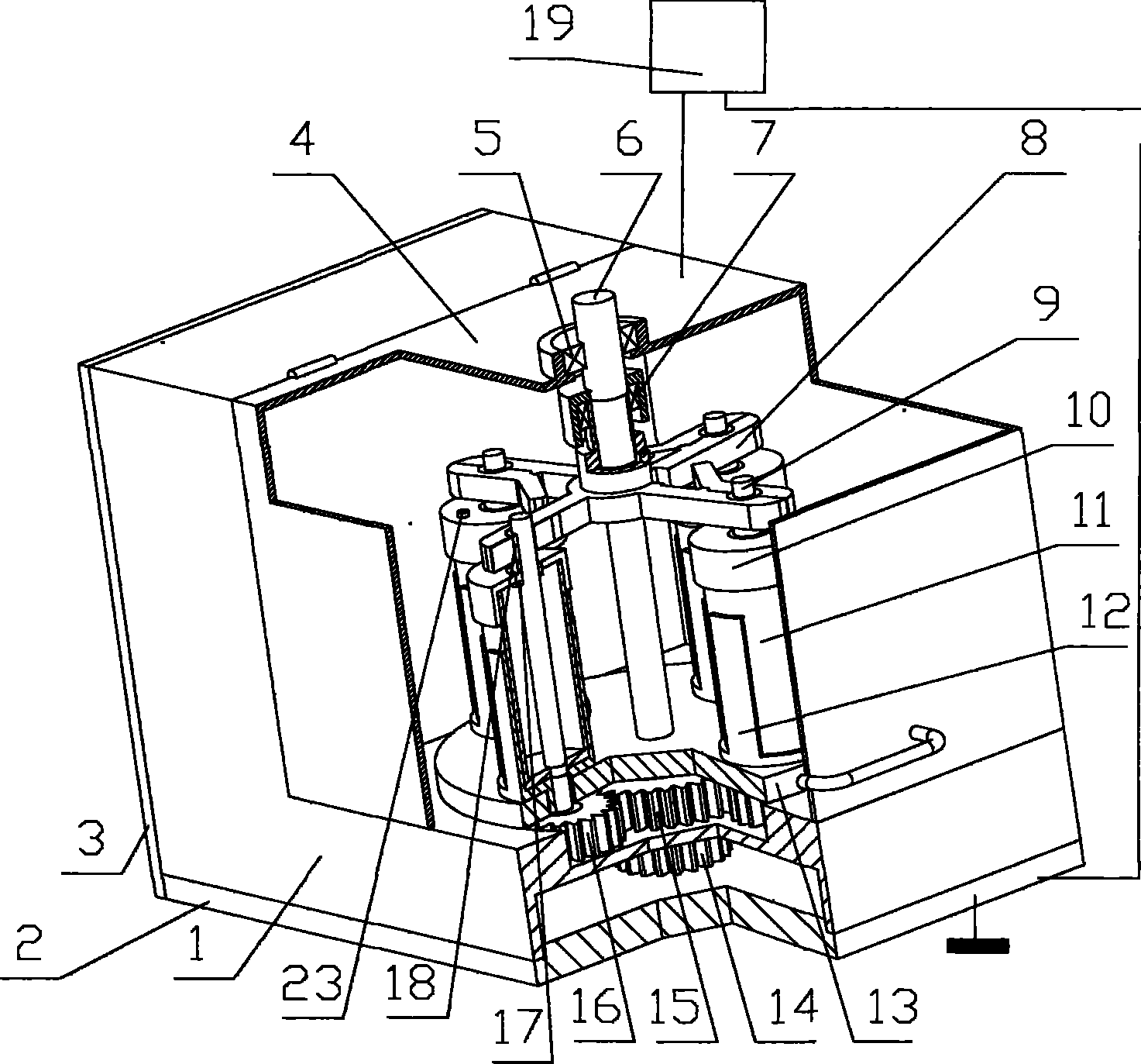
[0024] As shown in Fig. 1 and Fig. 2, the plasma-assisted high-energy planetary ball mill device consists of a chassis 1, a bottom cover 2, a side cover 3, an upper cover 4, an electrode connecting shaft upper bearing 5, an electrode connecting shaft 6, and an electrode connecting shaft when assembled vertically. Lower bearing 7, electrode clamping frame 8, electrode shaft 9, tank cover 10, ball mill tank body 11, tank body positioning seat 12, planetary disc 13, planetary disc drive wheel 14, sun gear 15, planetary gear 16, electrode sealing ring 17. The electrode bearing 18, the power supply 19, the intermediate wheel 20, the motor shaft gear 21, and the driving motor 22 are composed. Their connections are as follows:

[0025] The first part: the electrode shaft 9 is fixedly equipped with an electrode bearing 18, which is fixed on the tank cover 10 with air extraction holes through the electrode sealing ring 17, and the tank cover 10 is closely combined with the ball mill ta...

Embodiment 2

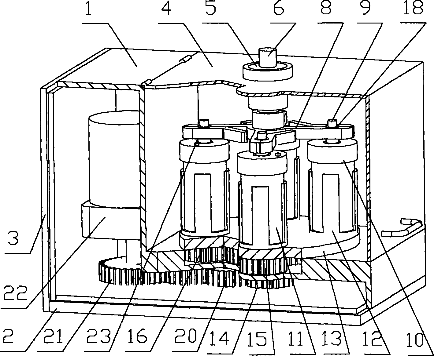
[0032]Fig. 4 is a schematic diagram of the structure of the plasma-assisted high-energy planetary ball mill when the electrodes are assembled horizontally to the shaft. The horizontal assembly of the electrode connecting shaft means that the electrode connecting shaft 6 passes through the side wall of the cabinet 1 through the upper bearing 5 of the electrode connecting shaft, and keeps rotating relative to the cabinet 1, and the lower bearing of the electrode connecting shaft is installed in the bearing hole at the right end of the electrode connecting shaft 6 7. It is flexibly connected with the electrode holding frame 8.

[0033] The connection, assembly relationship and working process of other parts are the same as in Embodiment 1.


PUM


Abstract

The invention relates to a high-energy ball mill technique, in particular a plasma-assistant high-energy ball mill device. The device is made by modification based on the traditional planet ball miller. The electrode shaft is secured on the can lid by an electrode seal ring, is connected movably with an electrode clamping frame by an electrode bear. The electrode clamping frame for claming the electrode shaft is mounted movably on one end of the planetary plate center shaft. The electrode clamping frame connects with an electrode spindle with a bearing pore at one end. The electrode spindle connects with the anode of the power source, and the cabinet connects with the cathode of the power source and is grounded. The invented technique introduces plasma into the planet ball miller, enhances the ball milling speed with a narrow distribution of particle size, and improves ball mill efficiency at the same time. The invented device is provided with a reliable and reasonable structure, and is easy to be produced. The application and popularization of the plasma-assistant high-energy ball mill technique in nano commercial scale production are promoted.

Description

technical field [0001] The invention relates to high-energy ball milling technology, and more specifically refers to a plasma-assisted high-energy planetary ball milling device. Background technique [0002] The planetary ball mill uses the rotation and revolution of the ball mill tank to drive the balls in the ball mill tank under the joint action of revolution centrifugal force, rotation centrifugal force and gravity. The magnitude and direction of the force on each point in the tank are constantly changing, and the trajectory is chaotic. , so that the grinding ball and the material to be ground collide violently and squeeze each other during high-speed operation, so as to achieve the purpose of grinding the material to be ground finely. Because of its compact structure, ability to grind different material powders, adjustable working conditions, and relatively high ball milling efficiency, it is widely used in mining, metallurgy, chemical industry, construction, electric p...

Claims


Application Information

Patent Timeline
Patent Type & Authority Patents(China)
IPC IPC(8): B02C17/08B02C17/18B02C19/18
Inventor 陈维平何曾先江帆杨超李元元
Owner SOUTH CHINA UNIV OF TECH
Why Eureka
Try Eureka