Steering wheel connection shaft staggering device

A technology for connecting shafts and steering wheels, applied in steering columns, steering controls, steering mechanisms, etc., can solve problems such as steering wheel damage to drivers, performance degradation, and insufficient rigidity, and achieve simple and reliable connection structures, high safety, and low cost.

Inactive Publication Date: 2017-02-08
ZHEJIANG RIBON INTELLIGENT EQUIP CO LTD
View PDF5 Cites 6 Cited by
  • Summary
  • Abstract
  • Description
  • Claims
  • Application Information

AI Technical Summary

Problems solved by technology

[0002] At present, in order to prevent the steering wheel from moving up and hurting the driver during the collision, a dislocation device is installed in the steering wheel connection shaft of the car. Once a collision occurs, the displacement can occur, which can effectively prevent the steering wheel from moving up. The current dislocation device uses the elasticity of the coil spring. When it hits, the error is relatively large, so the device has certain limitations. In addition, because the coil spring is exposed to the air for a long time, its performance will also decline. So there is a certain risk
[0003] In addition, there are some common car steering wheel connecting shafts. The rod body is divided into two parts. The two parts of the rod body are tangentially connected at the docking part, and then a set of coil springs are fastened outside the docking part of the two parts. The rigidity of the coil spring prevents the The two groups of rods are dislocated, and when a collision occurs, the coil springs are stretched due to insufficient rigidity of the coil springs, causing the two groups of rods to be dislocated, thereby preventing the phenomenon of the steering wheel from moving up and hurting the driver. However, the device still The self-rigidity of the material is used, and because the coil spring is exposed to the air for a long time, its performance will also decrease, so there is a certain danger

Method used


Image

  • Steering wheel connection shaft staggering device
  • Steering wheel connection shaft staggering device
  • Steering wheel connection shaft staggering device

Examples


Embodiment Construction

[0025] The following will clearly and completely describe the technical solutions in the embodiments of the present invention with reference to the accompanying drawings in the embodiments of the present invention. Obviously, the described embodiments are only some, not all, embodiments of the present invention. Based on the embodiments of the present invention, all other embodiments obtained by persons of ordinary skill in the art without making creative efforts belong to the protection scope of the present invention.

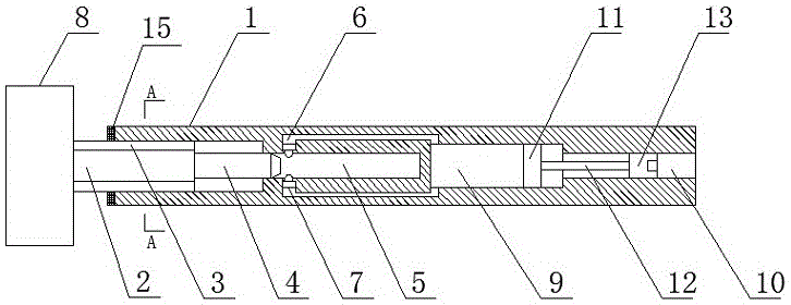
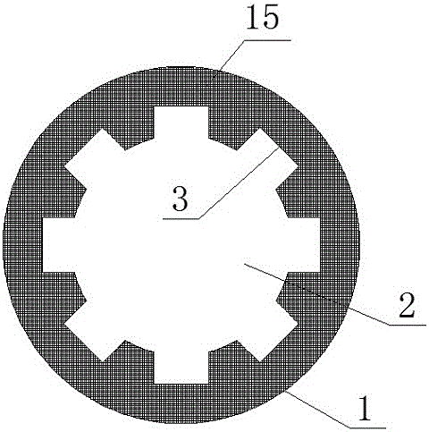
[0026] see figure 1 , figure 2 with image 3 , an embodiment provided by the present invention: a steering wheel connection shaft misalignment device, including a housing 1, a rotating shaft 2 and a gear 8 fixed at the bottom of the rotating shaft 2, the inside of the bottom of the housing 1 passes through the tooth structure 3 Connecting the side of the rotating shaft 2, the bottom surface of the bottom of the housing 1 is fixedly provided with an anti-col...


PUM


Abstract

The invention discloses a steering wheel connection shaft staggering device which comprises a shell, a rotating shaft and a gear fixed at the bottom of the rotating shaft, wherein the inside of the bottom of the shell is connected with the side surface of the rotating shaft through a tooth structure; an anti-collision gasket is fixedly arranged on the bottom surface of the bottom of the shell; the size of the anti-collision gasket is equal to that of the bottom surface of the bottom of the shell; a group of limiting shafts are fixed in the center of the top of the rotating shaft; a hollow structure for plugging the limiting shafts is formed inside the shell; a hollow region is formed in a position, located above the hollow structure, in the shell; a through hole structure for communicating the hollow region with the bottom of the hollow structure is arranged between the hollow region and the bottom of the hollow structure; a group of limiting heads are placed at a position, located at the bottom of the hollow structure, on the through hole structure; a group of pistons are arranged inside the hollow region; a group of connection rods are fixed in the centers of the tops of the pistons; the tops of the connection rods are connected with a group of threaded plates; the side surfaces of the threaded plates are connected into the shell through threaded structures. In case of collision, a staggering phenomenon is caused; furthermore, gas can be supplemented, and the service life is long.

Description

technical field [0001] The invention relates to the technical field of automobile mechanical parts, in particular to a steering wheel connecting shaft dislocation device. Background technique [0002] At present, in order to prevent the steering wheel from moving up and hurting the driver during the collision, a dislocation device is installed in the steering wheel connection shaft of the car. Once a collision occurs, the displacement can occur, which can effectively prevent the steering wheel from moving up. The current dislocation device uses the elasticity of the coil spring. When it hits, the error is relatively large, so the device has certain limitations. In addition, because the coil spring is exposed to the air for a long time, its performance will also decline. So there is a certain risk. [0003] In addition, there are some common car steering wheel connecting shafts. The rod body is divided into two parts. The two parts of the rod body are tangentially connected ...

Claims


Application Information

Patent Timeline
Patent Type & Authority Applications(China)
IPC IPC(8): B62D1/19
CPCB62D1/192
Inventor 刘玲燕
Owner ZHEJIANG RIBON INTELLIGENT EQUIP CO LTD
Why Eureka
Try Eureka