Clock ceiling lamp

A technology for ceiling lamps and clocks, which is applied to mechanically driven clocks, cooling/heating devices of lighting devices, lighting and heating equipment, etc. Effect, well-lit, simple maintenance effect

Active Publication Date: 2017-02-08
宋长宏
View PDF5 Cites 1 Cited by
  • Summary
  • Abstract
  • Description
  • Claims
  • Application Information

AI Technical Summary

Problems solved by technology

[0002] Now, ceiling lamps are installed in houses, and people can generally see them when looking up. However, the heat dissipation effect of ceiling lamps is not good, and it is easy to burn out due to overheating inside the lamp; Insufficient light, reflection, observation field of view and angle, etc., make it difficult for people (especially elderly people with limited mobility or bedridden) to check the time accurately and conveniently; in addition, ceiling lamps and clocks need to be installed separately in stages, and disassembly and maintenance are more cumbersome

Method used


Image

  • Clock ceiling lamp
  • Clock ceiling lamp
  • Clock ceiling lamp

Examples


Embodiment Construction

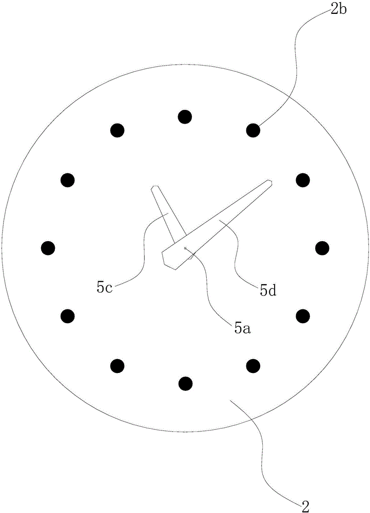
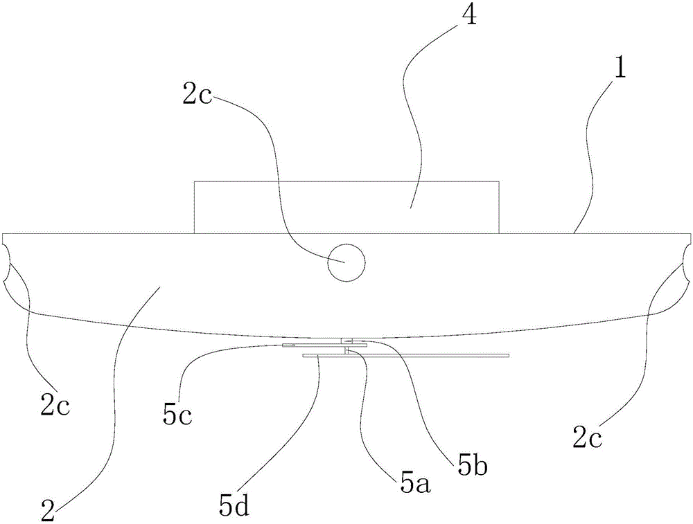
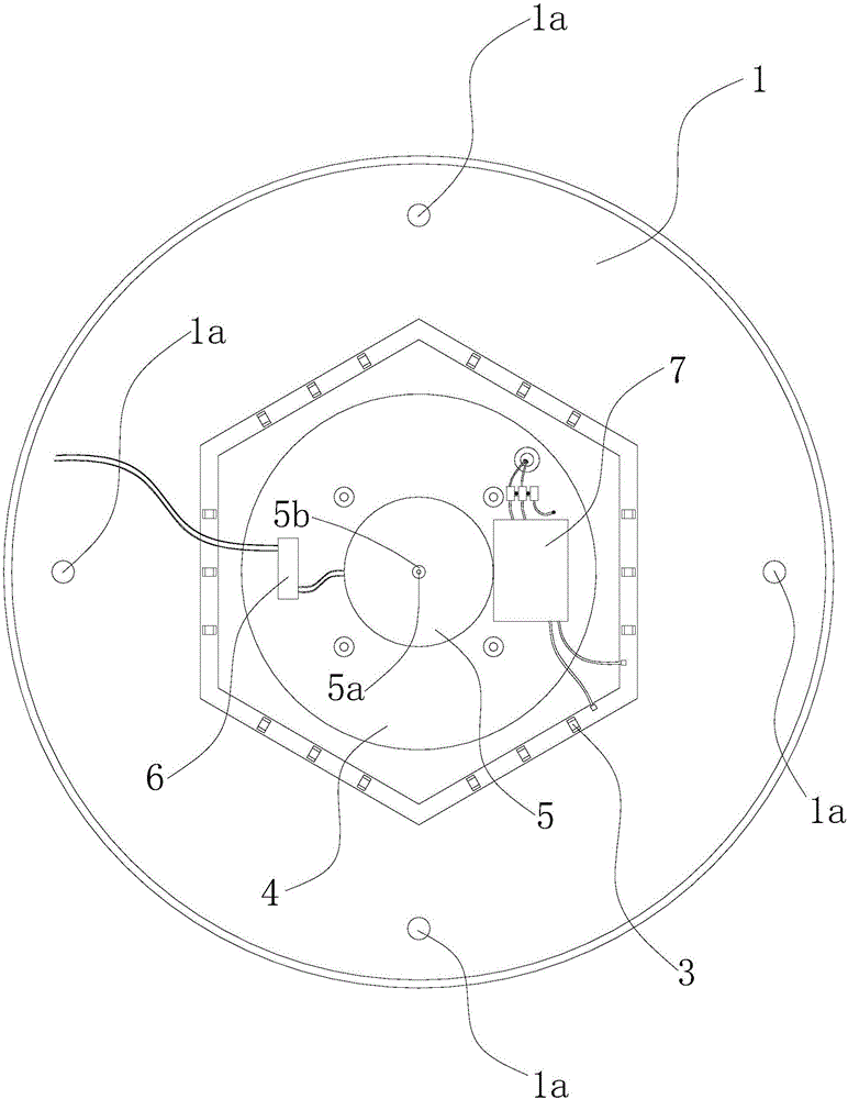
[0018] Such as Figure 1-4 As shown: the clock ceiling lamp includes a lamp holder 1, a lampshade 2 matched with the lamp holder 1, a luminous body 3, and a transformer device 7. A lampshade cabin 2a is formed between the lampholders 1, and the illuminant 3 is located in the lampshade cabin 2a and is arranged on the lower side of the lampholder 1, and the transformer 7 is electrically connected with the illuminant 3 ( Figure 4 Corresponding connecting wires are not shown).

[0019] The lamp holder 1 is an annular plate with a central hole in the middle area. The upper side of the lamp holder 1 is provided with a cylindrical mounting seat 4 coaxial with it and covering the central hole. The upper side of the mounting seat 4 is sealed and the lower side is open. The inner cavity of the mounting seat 4 communicates with the lampshade compartment 2a, the axial height of the mounting seat 4 is set to h, the maximum axial distance between the lamp holder 1 and the lampshade 2 is s...


PUM


Abstract

A clock ceiling lamp comprises a lamp base, a lampshade, a light emitting body and a power transformation device electrically connected with the light emitting body. A lampshade cabin is formed between the lampshade and the lamp base. The light emitting body is arranged on the lower side of the lamp base. The lamp base is an annular plate. An installing base with an inner cavity communicating with the lampshade cabin is arranged on the upper side of the lamp base. A clock movement is arranged at the middle portion of the upper side of the installing base. The movement is provided with a hollow shaft and a solid shaft, and the lower ends of the two shafts penetrate out of the lampshade, and the lower end of the hollow shaft and the lower end of the solid shaft are connected with an hour hand and a minute hand. The power transformation device and an electricity storage device are arranged on the inner upper side of the installing base and located on the two sides of the movement. Clock scales are arranged on the lower side face of the lampshade, and the lampshade is made of photovoltaic glass. The electric input end of the electricity storage device is connected with the electric output end of the lampshade, and the electric output end of the electricity storage device is connected with the electric input end of the movement. The lampshade and the lamp base are provided with a plurality of second ventilation holes and a plurality of first ventilation holes, and a heat dissipation channel is formed by the ventilation holes and the lampshade cabin. The clock ceiling lamp has two purposes, the heat dissipation effect of the lamp is improved, and people can accurately and conveniently check time, and dismounting, mounting and maintaining are simple.

Description

technical field [0001] The invention relates to a clock ceiling lamp. Background technique [0002] Now, ceiling lamps are installed in houses, and people can generally see them when looking up. However, the heat dissipation effect of ceiling lamps is not good, and it is easy to burn out due to overheating inside the lamp; Insufficient light, reflection, observation field of view and angle, etc., make it difficult for people (especially elderly people with limited mobility or bedridden) to check the time accurately and conveniently; in addition, ceiling lamps and clocks need to be installed separately in stages, making disassembly and maintenance more cumbersome. Contents of the invention [0003] The technical problem to be solved by the present invention is to provide a clock ceiling lamp. The clock ceiling lamp combines the ceiling lamp and the clock into one, which can be used for two purposes. It not only improves the heat dissipation effect of the lamp, but also enab...

Claims


Application Information

Patent Timeline
Patent Type & Authority Applications(China)
IPC IPC(8): F21S9/02F21V21/03F21V33/00F21V23/00F21V29/83G04B47/00F21Y115/10
CPCF21S9/02F21V21/03F21V23/023F21V23/026F21V29/83F21V33/00G04B47/00
Inventor 宋长宏
Owner 宋长宏
Why Eureka
Try Eureka