Wall-mounted type air purifier based on thermal regeneration and air purification method

An air purifier and air purification technology, which is applied in the field of indoor air purification, can solve problems such as excessive pressure, secondary pollution, and damage to devices, and achieve the effect of convenient operation, simple structure, and long-term effective indoor air purification

Inactive Publication Date: 2017-02-08
於铉
View PDF6 Cites 8 Cited by
  • Summary
  • Abstract
  • Description
  • Claims
  • Application Information

AI Technical Summary

Problems solved by technology

[0007] The use of heating and desorption of adsorption materials is a method commonly used by those skilled in the art. In order to overcome the defect that adsorption purifiers need to frequently replace adsorption materials, and according to the method of heating and desorption of adsorption materials, there are currently public literature records that use thermal desorption A new type of adsorption purifier that integrates functions, such as the patent application number: 201510898501.0, a wall-mounted air purifier based on thermal regeneration and its purification method. Users can choose indoor purification or mechanical ventilation according to their needs. When choosing indoor purification When the function is used, the sewage will be discharged after thermal desorption during the working process. When the mechanical ventilation function is selected, the outdoor fresh air will be introduced into the room. However, the wall-mounted air purifier and its purification method have the following defects: (1) because only when the heat desorption ( During the thermal regeneration mode period), the pressure in the closed airtight cabin may be too high, and because the pressure relief valve for preventing device damage is installed on the wall of the air purification room of the airtight cabin of the purifier, once the pressure relief valve is opened When the pressure is released, the air with a high concentration of pollutants in the cabin will be released to the room, causing secondary pollution in the room. The air valve is closed, that is, when the purifier is in the purification mode, the heating control circuit of the electric heating wire in the heating and regeneration chamber is out of control and generates high temperature, and the temperature sensor in the heating and regeneration chamber is damaged. At this time, the pressure generated in the closed heating and regeneration chamber It may be too large and damage the device, because the pressure relief valve installed on the wall of the air purification room facing the room cannot work; ⑵ cannot discharge the dust adsorbed on the coarse filter to the outside; ⑶ because it is opened in the sewage mode The most important thing is the air valve set at the top of the air cleaning room, and the closing is the air valve set at the bottom of the air cleaning room, so the desorbed air containing pollutants in the air cleaning room cannot be completely discharged, and it may also be discharged into the room, forming secondary air. (4) Since the air valve at the bottom of the air purification room is opened in the fresh air mode, and the air valve at the top of the air purification room is closed, it is impossible for outdoor fresh air to be introduced into the room after being purified by the filter module in the main body of the air duct , but directly into the room without purification by the filter module; (5) due to the use of pure timing sewage, the timing time may be too long or too short, such as the timing time may be too long in winter, and the timing time may be too short in summer the heat can't dissipate

Method used


Image

  • Wall-mounted type air purifier based on thermal regeneration and air purification method

Examples


Embodiment Construction

[0040] In order to better understand the technical content of the present invention, specific embodiments are given together with the attached drawings for description as follows.

[0041] Aspects of the invention are described in this disclosure with reference to the accompanying drawings, which show a number of illustrated embodiments. Embodiments of the present disclosure are not necessarily intended to include all aspects of the invention. It should be appreciated that the various concepts and embodiments described above, as well as those described in more detail below, can be implemented in any of numerous ways, since the concepts and embodiments disclosed herein are not limited to any implementation. In addition, some aspects of the present disclosure may be used alone or in any suitable combination with other aspects of the present disclosure.

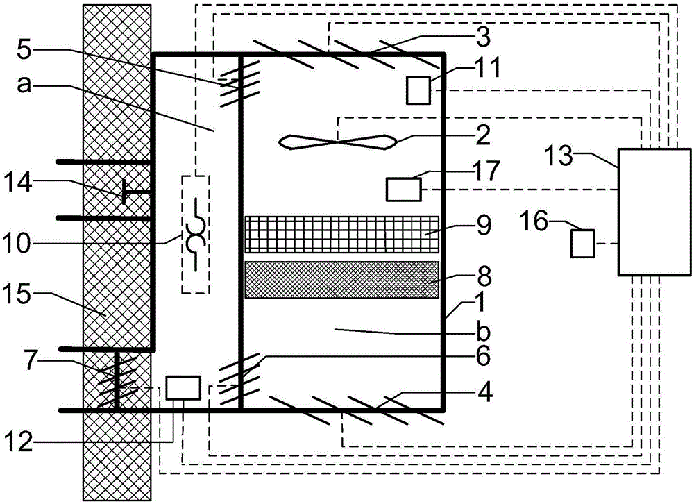
[0042] Such as figure 1 As shown, a wall-mounted air purifier based on thermal regeneration includes: a closed cabin 1, a f...


PUM


Abstract

The invention discloses a wall-mounted type air purifier based on thermal regeneration and an air purification method. The air purifier comprises a closed cabin divided into a left heating regeneration chamber and a right air purification chamber, a VOCs sensor, a bidirectional fan, efficient and regenerable VOCs and formaldehyde absorption materials, a low-efficient filter, a heating body, a first temperature sensor and five air valves controlling an air duct, wherein the VOCs sensor, the bidirectional fan, the efficient and regenerable VOCs and formaldehyde absorption materials and the low-efficient filter are sequentially installed in the air purification chamber from top to bottom; the heating body and the first temperature sensor are sequentially installed in the heating regeneration chamber from top to bottom; a pressure relief valve used for pressure relief is installed on a cabin wall of the heating regeneration chamber, communicates with the outdoor space by penetrating through the wall, and does not cause secondary pollution to the indoor space during pressure relief; a flow sensor is installed between the VOCs sensor and the fan; and a second temperature sensor is installed indoors. According to the method, during a pollution discharge period in the purification mode and in the fresh air mode, the wind direction of the fan is set and changed to discharge dust of the low-efficient filter outdoors. The pollution discharge duration is controlled through a timing and temperature measurement method, it is ensured that the temperature in the cabin is adaptive to the indoor temperature after pollution discharge, and an alarm is given when flow is unsmooth.

Description

technical field [0001] The invention belongs to the technical field of indoor air purification, and in particular relates to a structural design of a wall-mounted air purifier based on thermal regeneration and an air purification method. Background technique [0002] With the rapid development of urbanization in our country, the number of new buildings is huge every year, and more and more new decoration materials and chemical products are used in interior decoration. These new interior decoration materials often release a large amount of pollutants such as volatile organic compounds (VOCs) and formaldehyde, causing serious indoor pollution. According to statistics, after decoration, most of the formaldehyde and VOCs content in newly built houses exceeds the standard. [0003] Volatile organic compounds (VOCs) and formaldehyde significantly affect people's comfort, health and work efficiency. Volatile organic compounds cause sensory stimulation to the human body, make the ...

Claims


Application Information

Patent Timeline
Patent Type & Authority Applications(China)
IPC IPC(8): F24F1/02F24F3/16F24F11/00F24F13/28B01D53/04
CPCB01D53/0407B01D53/0454B01D2257/70B01D2257/708B01D2258/06B01D2259/4009F24F13/28F24F2221/17F24F2221/34F24F8/10F24F8/108
Inventor 於铉
Owner 於铉
Why Eureka
Try Eureka