
A method and system for measuring fluorescence lifetime

A technology of fluorescence lifetime and measurement method, applied in measurement devices, fluorescence/phosphorescence, material analysis by optical means, etc., can solve the problems of high technical requirements, and achieve the effect of relaxing technical requirements

Inactive Publication Date: 2019-04-09
GUANGDONG UNIV OF TECH
View PDF4 Cites 0 Cited by
  • Summary
  • Abstract
  • Description
  • Claims
  • Application Information

AI Technical Summary

Problems solved by technology

However, there is such a problem in the existing frequency domain heterodyne method that the frequency of the signal that modulates the gain of the image intensifier needs to be close to the high modulation frequency of the excitation light, which requires relatively high technical requirements for the image intensifier

Method used


Image

  • A method and system for measuring fluorescence lifetime
  • A method and system for measuring fluorescence lifetime
  • A method and system for measuring fluorescence lifetime

Examples


Embodiment Construction

[0048] In order to enable those skilled in the art to better understand the technical solutions in the present invention, the technical solutions in the embodiments of the present invention will be clearly and completely described below in conjunction with the drawings in the embodiments of the present invention. Obviously, the described The embodiments are only some of the embodiments of the present invention, not all of them. Based on the embodiments of the present invention, all other embodiments obtained by persons of ordinary skill in the art without making creative efforts shall fall within the protection scope of the present invention.

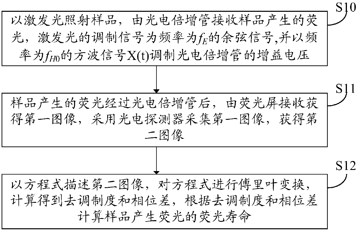
[0049] An embodiment of the present invention provides a fluorescence lifetime measurement method, including:

[0050] The sample is irradiated with excitation light, and the fluorescence generated by the sample is received by the photomultiplier tube, and the modulation signal of the excitation light is f E cosine signal, and with fre...


PUM


Abstract

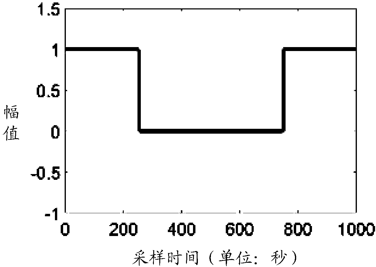
The invention discloses a method and a system for measuring fluorescence lifetime. The method comprises the following steps of irradiating a sample by exciting light, and enabling a photomultiplier to receive the fluorescence produced by the sample, wherein a modulation signal of the exciting light is a cosine signal with the frequency of fE; modulating the gain voltage of the photomultiplier by a square wave signal X(t) with frequency of fH0; after the fluorescence produced by the sample passes through the photomultiplier, enabling a fluorescence screen to receive a first image; enabling a photoelectric detector to collect the first image, so as to obtain a second image; according to the second image, calculating the fluorescence lifetime of the fluorescence produced by the sample. Compared with the prior art, the method and the system for measuring the fluorescence lifetime have the advantages that the fluorescence lifetime is measured through heterodyning high-order harmonic component modulation; the gain voltage of the photomultiplier is modulated by the low-frequency square wave signal, and the technical requirement on an image intensifier is decreased.

Description

technical field [0001] The invention relates to the technical field of fluorescence lifetime measurement, in particular to a fluorescence lifetime measurement method and system. Background technique [0002] Fluorescence lifetime refers to the average time for fluorescent molecules to stay in the excited state, which is not only related to the structure of the molecule itself, but also related to the polarity and viscosity of the microenvironment where the molecule is located. Therefore, by measuring the fluorescence lifetime, we can directly understand the changes in the environment of fluorescent molecules, and have a wide range of applications in biophysics, biochemistry, and clinical medical diagnosis. [0003] The measurement of fluorescence lifetime includes two realization methods: time domain method and frequency domain method. Compared with the time-domain method, the frequency-domain method has low hardware cost and high measurement efficiency, and can quickly obt...

Claims


Application Information

Patent Timeline
Patent Type & Authority Patents(China)
IPC IPC(8): G01N21/64
CPCG01N21/6402
Inventor 卢凯欣白玉磊周延周
Owner GUANGDONG UNIV OF TECH
Learn More