
Exit pupil distance adjusting mechanism for head-mounted visual equipment and assembly method

A technology for adjusting mechanism and exit pupil distance, applied in metal processing equipment, assembly machines, optics, etc., can solve problems such as fixed, no exit pupil distance adjustment mechanism, eye fatigue, etc., to increase experience effect, easy to adjust and fix line effect

Active Publication Date: 2017-02-08
GEER TECH CO LTD
View PDF5 Cites 11 Cited by
  • Summary
  • Abstract
  • Description
  • Claims
  • Application Information

AI Technical Summary

Problems solved by technology

However, most of the current head-mounted visual devices do not have an exit pupil distance adjustment mechanism. The exit pupil distance is fixed, and the headband is directly worn on the head, and the headband is fixed on the left and right sides of the visual device.
This kind of existence has a very big disadvantage, that is, it is impossible to adjust the appropriate exit pupil distance according to different people.
When a person wears a visual device, if the exit pupil distance is not suitable for a long time, symptoms such as eye fatigue and dizziness will occur, which will seriously affect the health of the eyes and the experience of the visual device.

Method used


Image

  • Exit pupil distance adjusting mechanism for head-mounted visual equipment and assembly method
  • Exit pupil distance adjusting mechanism for head-mounted visual equipment and assembly method
  • Exit pupil distance adjusting mechanism for head-mounted visual equipment and assembly method

Examples


Embodiment Construction

[0048] To make the objectives, technical solutions, and advantages of the embodiments of the present invention clearer, the technical solutions in the embodiments of the present invention will be described clearly and completely in conjunction with the accompanying drawings in the embodiments of the present invention.

[0049] In the description of the present invention, it should be noted that the orientation or positional relationship indicated by the terms "inner", "upper", "lower", "left", "right", etc. are based on the positional relationship shown in the drawings, and only It is for the convenience of describing the present invention and simplifying the description, rather than indicating or implying that the pointed device or element must have a specific orientation, be constructed and operated in a specific orientation, and therefore cannot be understood as a limitation of the present invention. In addition, the terms "first" and "second" are only used for descriptive purp...


PUM


Abstract

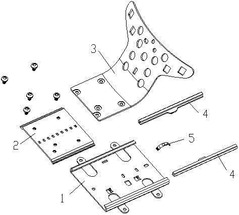
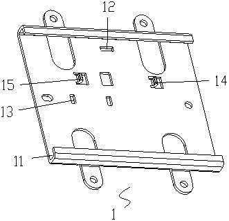
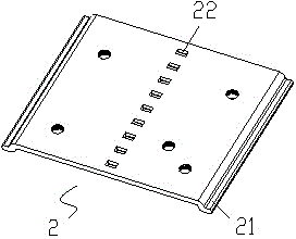
The invention provides an exit pupil distance adjusting mechanism for head-mounted visual equipment and an assembly method. The exit pupil distance adjusting mechanism comprises a support frame, a sliding plate and a head band holder. The sliding plate is arranged on the support frame in a front-back sliding mode. The head band holder is fixed on the sliding plate. A positioning structure used for adjusting and positioning sliding of the sliding plate is arranged between the sliding plate and the support frame. As the support frame, the sliding plate and the head band holder are arranged, a user can fix a head band on the head and fix the support frame on head-mounted visual equipment, the sliding plate slides frontward and backward on the support frame so the distance between the eyes of the user and the head-mounted visual equipment can be adjusted (namely, the exit pupil distance can be adjusted), and the user can adjust the exit pupil distance as needed to achieve a healthy way of eye use. After the sliding plate is adjusted through front-back sliding on the sliding plate, the sliding plate is positioned and fixed by the positioning structure, the adjusted exit pupil distance is kept, and thus, the exit pupil distance is simple and easy to adjust and fix.

Description

Technical field [0001] The present invention belongs to the technical field of head-mounted visual equipment, and specifically relates to an exit pupil distance adjustment mechanism for head-mounted visual equipment and an assembly method of the exit pupil distance adjustment mechanism. Background technique [0002] The exit pupil distance refers to the distance from the vertex of the last surface of the optical system to the intersection of the exit pupil plane and the optical axis. In head-mounted visual equipment, it can be considered as the distance from the eye to the lens. However, most current head-mounted visual devices do not have an exit pupil distance adjustment mechanism. The exit pupil distance is fixed. The headband is directly worn on the head, and the headband is fixed on the left and right sides of the visual device. This has a very big disadvantage, that is, it is impossible to adjust the appropriate exit pupil distance according to different people. When a pe...

Claims


Application Information

Patent Timeline
Patent Type & Authority Applications(China)
IPC IPC(8): G02B27/01B23P21/00
CPCB23P21/00G02B27/0176
Inventor 王良
Owner GEER TECH CO LTD
Learn More