Bed changing device for bedridden patients

A patient and support rod technology, applied in the field of bed changing devices for bedridden patients, can solve problems such as simple and inconvenient equipment, secondary dangers, and aggravated injuries, so as to reduce injuries and discomfort, reduce costs and processing costs, and improve The effect of work efficiency

Inactive Publication Date: 2017-02-15
SHANGHAI DIANJI UNIV
View PDF6 Cites 0 Cited by
  • Summary
  • Abstract
  • Description
  • Claims
  • Application Information

AI Technical Summary

Problems solved by technology

[0002] In the clinical nursing work of the hospital, nurses will help many patients change beds. Most of them use stretchers, wheelchairs, or multiple nurses to lift, hold, and lift patients to transfer beds, which is extremely inconvenient.
Especially for patients who are seriously ill, comatose in shock, or suffering from fracture pain, who should not move too much, or patients who need to brake, and have various drainage tubes left on their bodies after surgery, it is inevitable that they will suffer from excessive movement during the process of changing beds. Large or difficult to carry due to insufficient manpower
[0003] The existing equipment is too simple and inconvenient. When carrying the patient, the injury on the patient's body will be aggravated, various pipes will fall off, etc., which will cause secondary danger and aggravate the condition.
At the same time, changing beds for bedridden patients has greatly increased the workload and labor intensity of hospital nurses, and the body is vulnerable to injury in the long run

Method used


Image

  • Bed changing device for bedridden patients
  • Bed changing device for bedridden patients
  • Bed changing device for bedridden patients

Examples


Embodiment Construction

[0025] In order to make the technical means, creative features, goals and effects achieved by the present invention easy to understand, the present invention will be further described below in conjunction with specific embodiments.

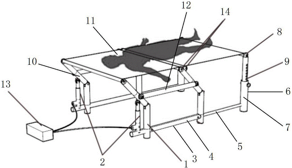
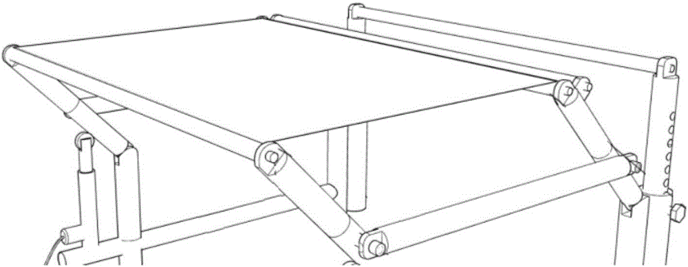
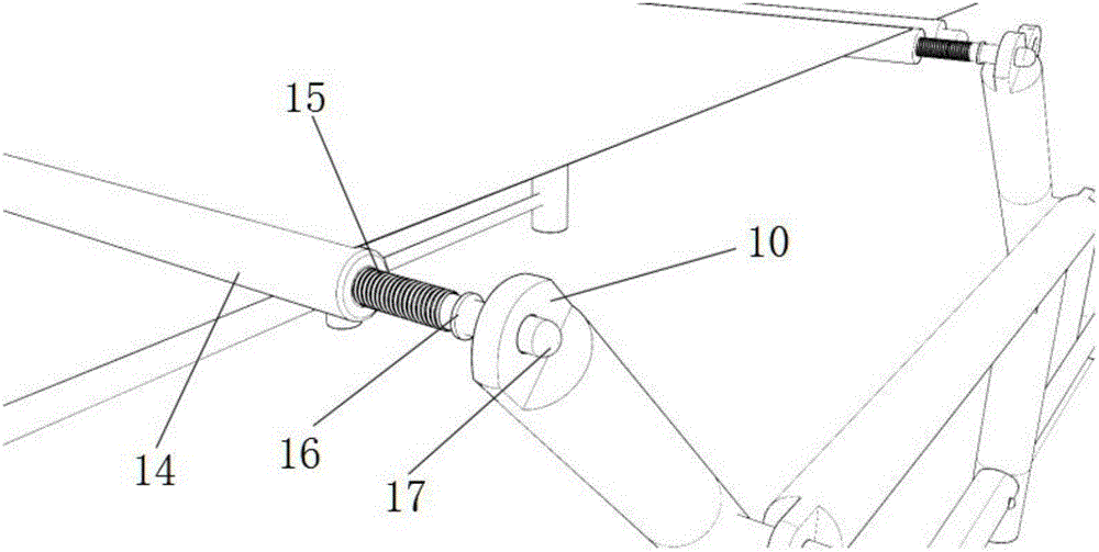
[0026] see figure 1 , figure 2 , image 3 and Figure 4 As shown, a bed changing device suitable for bedridden patients according to the present invention includes a set of bottom support rods 1 arranged oppositely, and one side of the bottom support rods 1 extends outward to form an installation end. A hydraulic cylinder 2 is installed on the installation end, and a shrinkage rod 3 is provided on the other side of the bottom pole 1. The shrinkage rod 3 includes a fixed end 4 fixedly connected with the bottom pole 1, and a 4 is used to connect the telescopic end 5 of the latch rod 6, the latch rod 6 includes a base 7 connected to the telescopic end 5, and an adjustment rod 8 arranged on the base 7, on the adjustment rod 8 There are several li...


PUM


Abstract

The invention discloses a bed changing device for bedridden patients. The bed changing device comprises a group of oppositely-arranged bottom support rods, one side of each bottom support rod extends outwards to form an installation end, hydraulic cylinders are installed at the installation ends, the other end of each bottom support rod is provided with a telescopic rod, each telescopic rod comprises a fixed end fixedly connected with the corresponding bottom support rod and a telescopic end which is located at the fixed end and used for being connected with a plug pin rod, and each plug pin rod comprises a base connected with the corresponding telescopic end and a regulating rod arranged on the base, wherein a plurality of limiting holes for regulating the height of the plug pin rod are formed in the regulating rod; the tops of the bottom support rods are provided with cranks, the bottom ends of the cranks are movably installed in grooves formed in the tops of the bottom support rods, push rods of the hydraulic cylinders are connected with the cranks and can push the cranks to rotate along the joints of the cranks and the grooves, and a canvas support is connected to the tops of the cranks.

Description

technical field [0001] The invention relates to the field of medical care, in particular to a bed changing device suitable for bedridden patients. Background technique [0002] In the clinical nursing work of the hospital, nurses will help many patients change beds. Most of them use stretchers, wheelchairs or multiple nurses to lift, hold, and lift patients to transfer beds, which is extremely inconvenient. Especially for patients who are seriously ill, comatose in shock, or suffering from fracture pain, who should not move too much, or patients who need to brake, and have various drainage tubes left on their bodies after surgery, it is inevitable that they will suffer from excessive movement during the process of changing beds. Large or difficult to carry due to lack of manpower. [0003] The existing equipment is too simple and inconvenient, and when the patient is transported, the injury on the patient's body will be aggravated, various pipes will fall off, etc., resulti...

Claims


Application Information

Patent Timeline
Patent Type & Authority Applications(China)
IPC IPC(8): A61G7/12
CPCA61G7/1019A61G7/1073
Inventor 王琦林劲羽姚志陈亨元
Owner SHANGHAI DIANJI UNIV
Why Eureka
Try Eureka