
Movable centre structure

An elastic tip and tip sleeve technology, applied in the direction of tailstock/tip, turning equipment, tool holder accessories, etc., can solve the problem of not being able to achieve axial expansion and contraction, etc.

Inactive Publication Date: 2017-02-15
南京路博利尔精密机械有限公司
View PDF0 Cites 0 Cited by
  • Summary
  • Abstract
  • Description
  • Claims
  • Application Information

AI Technical Summary

Problems solved by technology

It can be seen from the above that the existing conventional top can only rotate along the central axis at most, but cannot achieve axial expansion and contraction

Method used


Image

  • Movable centre structure

Examples


Embodiment Construction

[0014] The present invention is further illustrated below. It should be understood that the following specific embodiments are only used to illustrate the present invention and are not intended to limit the scope of the present invention. After reading the present invention, those skilled in the art can modify various equivalent forms of the present invention. fall within the scope defined by the appended claims of this application.

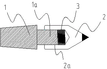
[0015] The invention discloses an elastic top structure, which is characterized in that: the elastic top structure includes a top seat 1, a top cover 2 and a spring 3, and the structure is that the top cover 2 is set on the top seat 1, and is connected with the top seat 1 It is a sliding fit, and the spring 3 is arranged between the center sleeve 2 and the center seat 1 .

[0016] As a preference, the tip sleeve 2 has a 60-degree taper on one side, and a counterbore 2a with a diameter of 20mm and a depth of 20mm on the other end surface, and the ...


PUM


Abstract

The invention discloses a movable centre structure. The movable centre structure comprises a centre base, a centre sleeve and a spring, wherein the centre sleeve is arranged on the centre base in a sleeving mode and is matched with the centre base in a sliding mode, and the spring is arranged between the centre sleeve and the centre base. According to the movable centre structure, a fixed mode of the centre structure of a machine tool headstock can be changed into an axially-telescopic and adjustable mode, and therefore the clamping mode and the driving mode between a machine tool and parts are enriched.

Description

technical field [0001] The invention relates to a mechanical product, especially a tip structure. Background technique [0002] Top, the machine tool part in machining, has two types: fixed top and movable top. The fixed center can support parts with complex end faces and parts that do not allow center holes. The top is mainly composed of a thimble, a clamping device, a housing, a fixed pin, a bearing and a mandrel. One end of the tip can touch the center hole or the inner hole of the pipe material, and the other end can be a part with a spherical or conical top surface, and the tip is fixed by a clamping device. When the part does not allow or cannot punch the center hole, the turning can be clamped directly with the clamping device. The shell and the mandrel are drilled with pin holes, and the fixing pins are used to insert or remove them to realize the two functions of life and death of the top. Tips can also be used for drilling, setting and reaming of workpieces. I...

Claims


Application Information

Patent Timeline
Patent Type & Authority Applications(China)
IPC IPC(8): B23B23/02
CPCB23B23/025
Inventor 于景国其他发明人请求不公开姓名
Owner 南京路博利尔精密机械有限公司
Learn More