
A circuit board clamping device

A fixture device and circuit board technology, which is applied to auxiliary devices, devices for coating liquid on surfaces, manufacturing tools, etc., can solve the problems of high cost, inability to detect whether the circuit board is properly clamped, and inability to prevent repeated gluing of the circuit board, etc. Achieve the effect of reducing dispensing and welding costs

Active Publication Date: 2019-01-18
GUANGDONG ELECTRONICS TECH RES INST
View PDF6 Cites 0 Cited by
  • Summary
  • Abstract
  • Description
  • Claims
  • Application Information

AI Technical Summary

Problems solved by technology

There are following deficiencies in the existing circuit board fixture device: first, the existing circuit board fixture device can only fix the circuit board on a plane, and the glue dispenser and welding machine can only plane dispensing and welding. Gluing and welding; Second, the existing circuit board fixture device needs to customize a specific mold for each circuit board with plastic, aluminum and other materials to fix the circuit board in the mold and use the mold as a glue dispenser The positioning reference for welding with the welding machine will cost more for customers with multiple types of circuit boards; third, the existing circuit board fixture device cannot detect whether the circuit board is clamped properly, nor can it prevent the circuit board from being repeatedly printed. glue

Method used


Image

  • A circuit board clamping device
  • A circuit board clamping device
  • A circuit board clamping device

Examples


Embodiment Construction

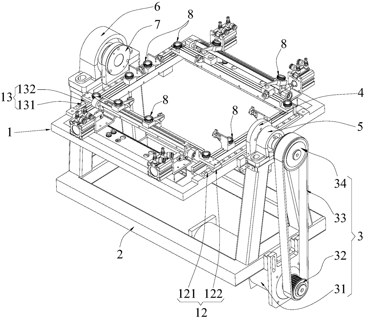
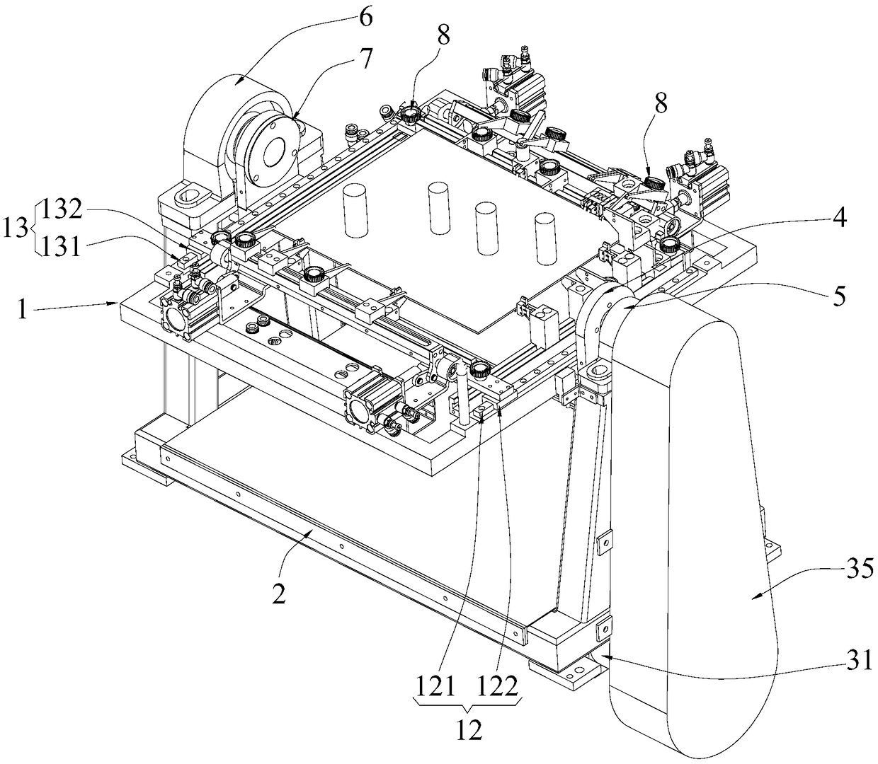
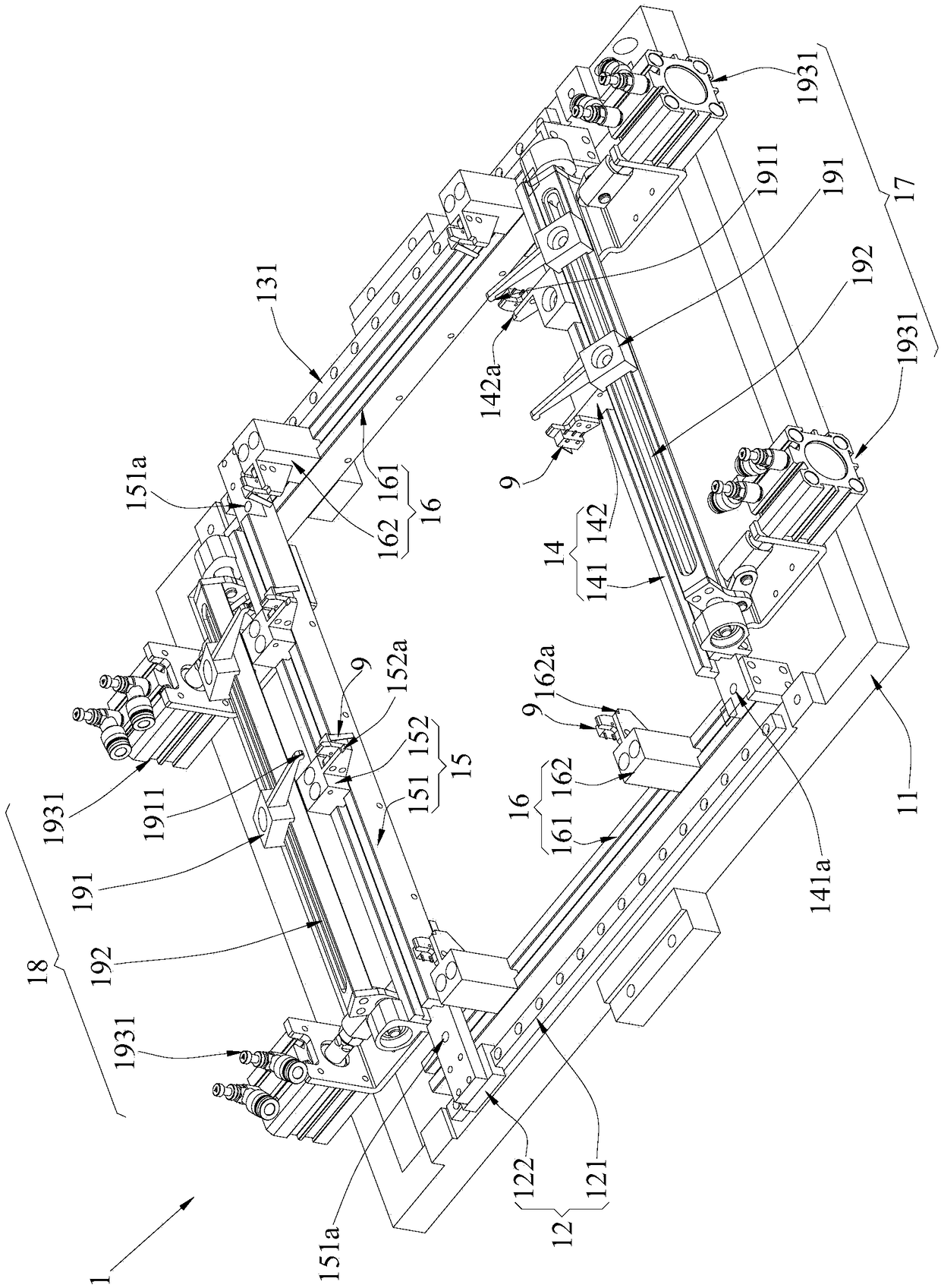
[0026] Such as Figure 1 to Figure 7As shown, the circuit board fixture device of the present invention is provided with a rotary table assembly 1, a fixture frame 2, a power system 3, a driving shaft assembly 4, a driving shaft bearing seat 5, a driven shaft bearing seat 6, and a driven shaft assembly 7 And detection system, wherein, the rotating table assembly 1 can clamp and fix the circuit board; the driving shaft bearing seat 5 and the driven shaft bearing seat 6 are fixed on the fixture frame 2 in a coaxial manner, and the driving shaft assembly 4 is installed on the driving shaft On the bearing seat 5, the driven shaft assembly 7 is installed on the driven shaft bearing seat 6, the turntable assembly 1 is fixed between the driving shaft assembly 4 and the driven shaft assembly 7, and the power system 3 and the fixture frame 2 are relatively fixed, Moreover, the power system 3 can drive the turntable assembly 1 to rotate at any angle around the axis of the drive shaft be...


PUM


Abstract

The invention discloses a clamp device for a circuit board. The clamp device is provided with a rotary table assembly, a clamp rack, a power system, a driving shaft assembly, a driving shaft bearing seat, a driven shaft bearing seat and a driven shaft assembly, wherein the rotary table assembly can clamp and fix the circuit board; the driving shaft bearing seat and the driven shaft bearing seat are fixed to the clamp rack coaxially; the driving shaft assembly is mounted on the driving shaft bearing seat, and the driven shaft assembly is mounted on the driven shaft bearing seat; the rotary table assembly is fixed between the driving shaft bearing seat and the driven shaft bearing seat; and the power system is fixed relative to the clamp rack and can drive the driving shaft assembly to drive the clamp rack to rotate around the axis of the driving shaft bearing seat by any angles. According to the clamp device for the circuit board, any glue dispensing or welding angles can be provided for a glue dispensing machine or a welding machine, so that high-complexity glue dispensing and welding are completed.

Description

technical field [0001] The invention relates to a circuit board clamping device, which can be used for clamping the circuit board during the work of a glue dispensing machine and a welding machine. Background technique [0002] In the glue dispensing and welding operations of the circuit board, it is necessary to use the circuit board fixture device to clamp and fix the circuit board so that the glue dispenser and the welding machine can work. There are following deficiencies in the existing circuit board fixture device: first, the existing circuit board fixture device can only fix the circuit board on a plane, and the glue dispenser and welding machine can only plane dispensing and welding. Gluing and welding; Second, the existing circuit board fixture device needs to customize a specific mold for each circuit board with plastic, aluminum and other materials to fix the circuit board in the mold and use the mold as a glue dispenser The positioning reference for welding with...

Claims


Application Information

Patent Timeline
Patent Type & Authority Patents(China)
IPC IPC(8): B23K3/08B05C13/02
CPCB05C13/02B23K3/087
Inventor 傅江成袁勇黄煜烽钟锐曾西敏黄雁东胡金华李宗高
Owner GUANGDONG ELECTRONICS TECH RES INST
Learn More