Floating jaw chuck of grinding machine

A technology of floating jaws and grinding machines, which is applied in the direction of grinding drive devices, grinding machine parts, grinding/polishing equipment, etc., which can solve the problem of restricting the use of chucks, no deflection of the bottom jaws, and the inability to produce floating self-aligning functions and other problems, to achieve the effect of strengthening self-aligning positioning ability

Active Publication Date: 2017-02-15
CHANGZHOU BEIDEFU MACHINERY SCI & TECH
View PDF5 Cites 2 Cited by
  • Summary
  • Abstract
  • Description
  • Claims
  • Application Information

AI Technical Summary

Problems solved by technology

[0003] The technical problem to be solved by the present invention is: in order to solve the limitation of the existing grinding machine chuck due to its own structure, when the shape of the processed workpiece is not concentric with the center positioning reference, the floating centering function cannot be produced, and the bottom jaw has no deflection function. Poor positioning ability, etc., greatly limit the use of the chuck. The invention provides a floating jaw chuck for grinding machines. The driving device drives the active section of the active section and the L-shaped crank of the passive section

Method used


Image

  • Floating jaw chuck of grinding machine
  • Floating jaw chuck of grinding machine
  • Floating jaw chuck of grinding machine

Examples


Embodiment Construction

[0034] The present invention is described in further detail now in conjunction with accompanying drawing. These drawings are all simplified schematic diagrams, which only illustrate the basic structure of the present invention in a schematic manner, so they only show the configurations related to the present invention. Wherein the piston movement direction is the upward direction, the opposite direction is the downward direction, and the plane perpendicular to the upward direction is the horizontal plane.

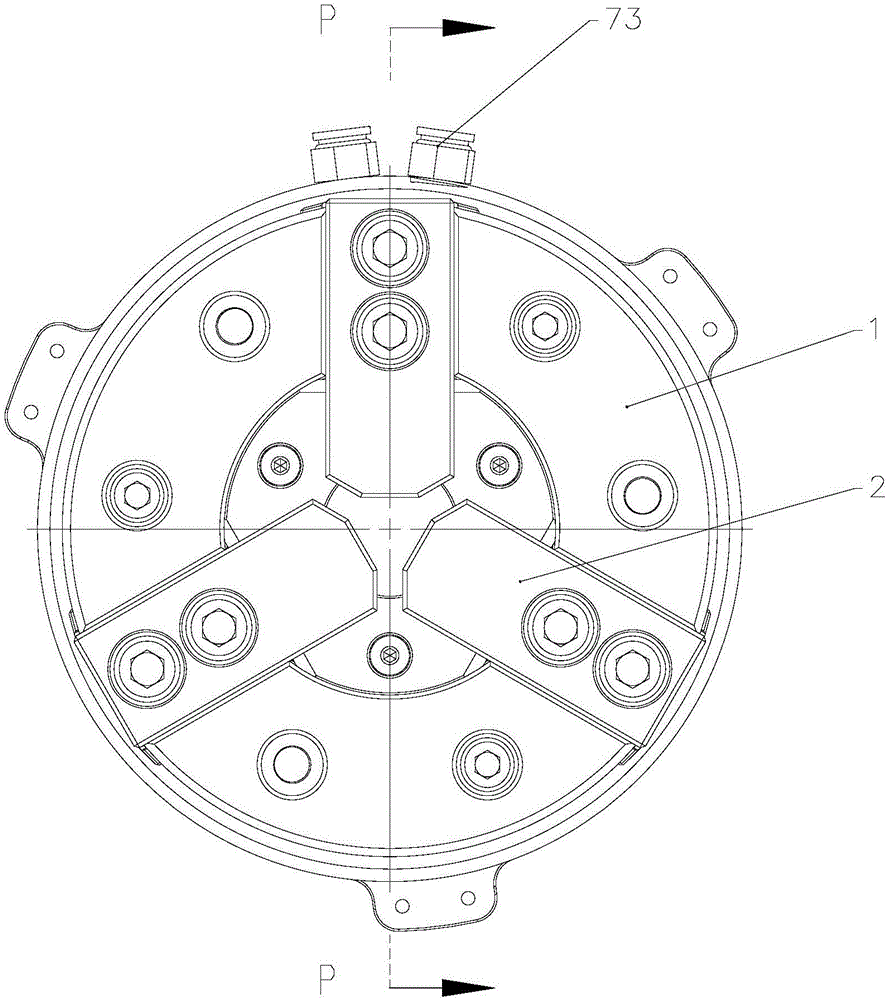
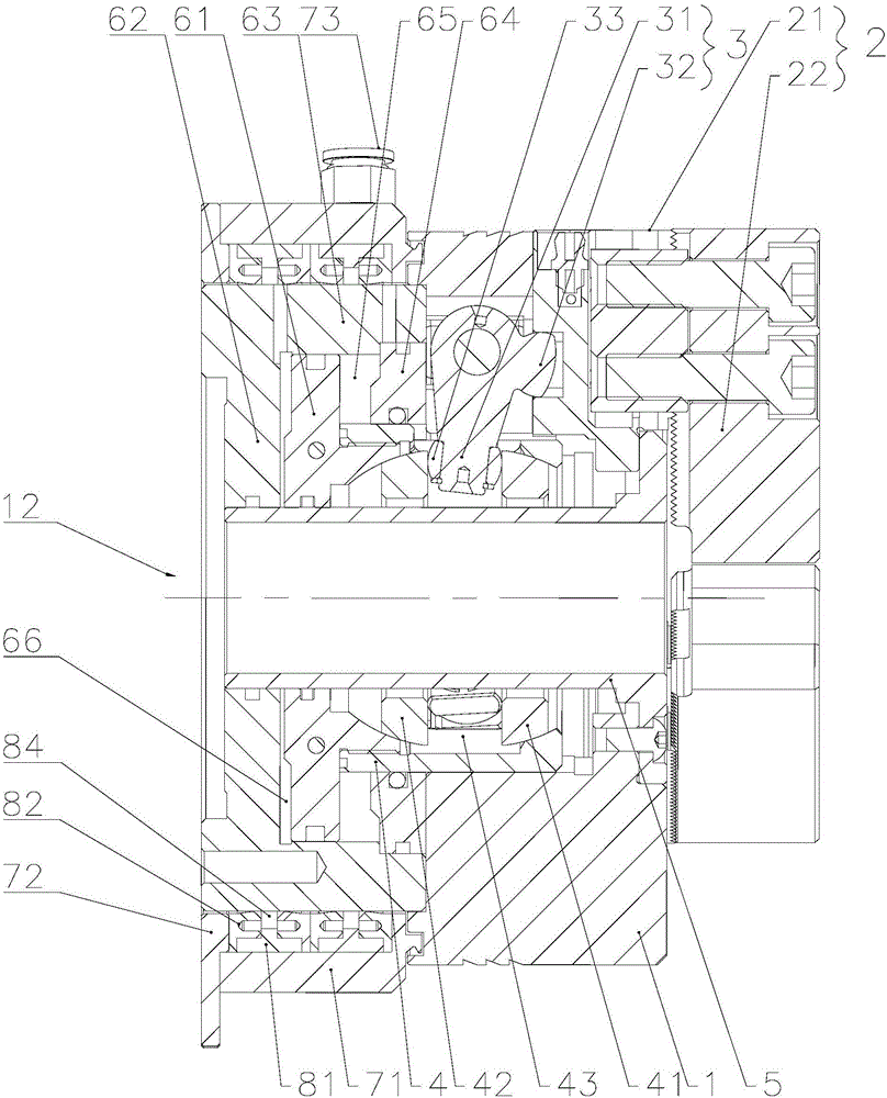
[0035] Such as Figure 1-5 Shown, a grinding machine floating jaw chuck, including:

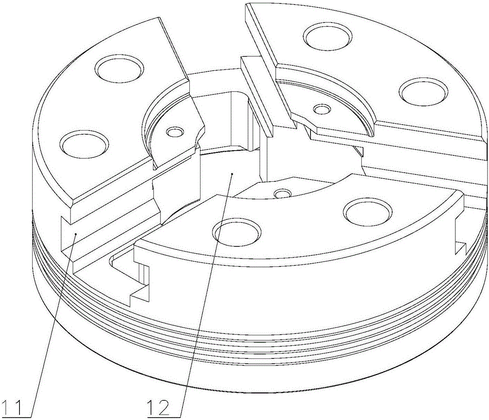
[0036] The disc body 1 is provided with at least two T-shaped grooves 11 in the horizontal direction, and the disc body 1 has a shaft hole 12 in the center,

[0037] The claw 2, the claw 2 includes a fixed bottom claw 21 and an upper claw 22, the bottom claw 21 includes a bottom claw plate 211 and a driving groove 212 arranged at the bottom of the bottom claw plate 211, and the bottom cl...


PUM


Abstract

The invention relates to the technical field of jigs, in particular to a floating jaw chuck of a grinding machine. The floating jaw chuck comprises a chuck body, clamping jaws, a crank, an inner sleeve and a drive device; the included angle between an active section and a passive section of the crank is 70-110 degrees, and one end of the active section is fixedly connected to a spherical floating head; the clamping jaws are arranged in T-shaped grooves through bottom jaw sliding blocks in a sliding mode; the inner sleeve is arranged in a shaft hole of the chuck body in a sliding mode; the crank is hinged to the chuck body through the joint of the active section and the passive section so that the passive section can be arranged in drive grooves below bottom jaw plates, and the spherical floating head on the active section is arranged in a ball clamping space formed between an upper ball sleeve and a lower ball sleeve; and the drive device is fixed to the lower side of the chuck body and is used for driving the inner sleeve to move up and down. According to the floating jaw chuck of the grinding machine, after work-pieces to be machined are clamped, bottom jaws can deflect to a large extent due to large floating amount, and the positioning ability is high.

Description

technical field [0001] The invention relates to the technical field of machine tool clamps, in particular to a grinding machine floating claw chuck. Background technique [0002] The existing mechanical grinding machine chuck is limited by its own structure. When the shape of the processed workpiece is not concentric with the center positioning reference, it cannot produce floating alignment, the bottom jaw has no deflection function, and the positioning ability is poor, so automatic clamping cannot be realized. Function, which greatly limits the degree of automation of the equipment, low efficiency and poor cutting accuracy. Contents of the invention [0003] The technical problem to be solved by the present invention is: in order to solve the limitation of the existing grinding machine chuck due to its own structure, when the shape of the processed workpiece is not concentric with the center positioning reference, the floating centering function cannot be produced, and t...

Claims


Application Information

Patent Timeline
IPC IPC(8): B24B37/27B24B47/00
CPCB24B37/27B24B47/00
Inventor 孙贤青孙贤良李传飞刘小成
Owner CHANGZHOU BEIDEFU MACHINERY SCI & TECH
Why Eureka
Try Eureka