Bridge bracing device with bracing surface capable of being enlarged

A support device and support surface technology, applied in the direction of lifting devices, lifting frames, etc., can solve the problems that the device cannot move, waste manpower and material resources, increase the support area, etc., achieve excellent support performance, increase service life, increase The effect of the support surface

Inactive Publication Date: 2017-02-15
卿琦
View PDF6 Cites 10 Cited by
  • Summary
  • Abstract
  • Description
  • Claims
  • Application Information

AI Technical Summary

Problems solved by technology

[0002] For building construction, we often encounter some road and bridge construction operations, which will encounter the construction and maintenance of tunnels or door openings, and when it comes to such construction operations, we often use a load-bearing system for facilities such as tunnels or door openings. As the support and protection of the facility, the general method is to set up a lifting bracket under the door opening that needs to be lifted, but this method is cumbersome, and the workload is large, the construction period is long, and a lot of manpower will be wasted. material resources
[0003] In order to solve the problem of erecting a jacking bracket under a door opening that needs to be jacked up, but this method is cumbersome, and the workload is large, the construction period is long, and a lot of manpower and material resources will be wasted. The Chinese invention CN 205421023 U discloses a road bridge The supporting device includes a base, a groove is provided on the base, a hydraulic cylinder is provided in the groove, a column is provided on the top of the hydraulic cylinder, a lifting pla

Method used


Image

  • Bridge bracing device with bracing surface capable of being enlarged
  • Bridge bracing device with bracing surface capable of being enlarged
  • Bridge bracing device with bracing surface capable of being enlarged

Examples


Example Embodiment

[0017] The technical solution of this patent will be described in further detail below in conjunction with specific embodiments.
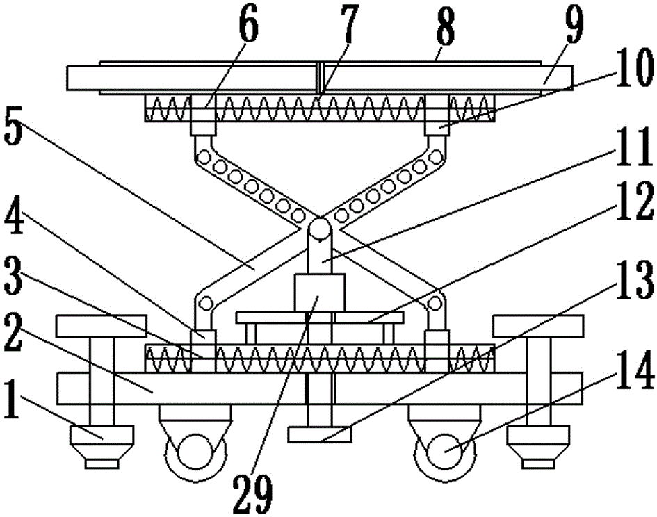
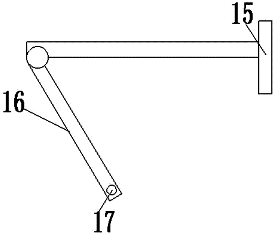
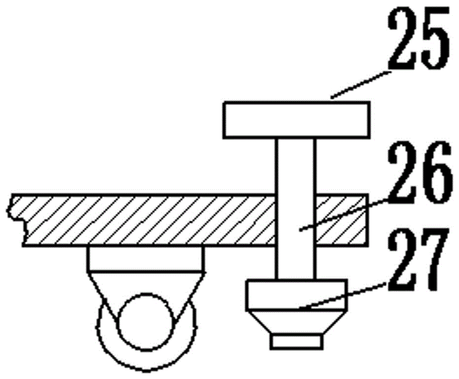
[0018] See Figure 1-5 , A bridge support device capable of expanding the supporting surface, including a base 2; the top of the base 2 is provided with a first slide rail 3 and a supporting plate 12 for supporting the entire device; the bottom of the base 2 is provided with a universal wheel 14; The base 2 is provided with a fixing device 1; the supporting plate 12 is arranged on the center line of the base 2 and is fixedly connected to the supporting plate 12 for supporting and fixing the rotary lifting device 29; the top of the supporting plate 12 is provided with a rotary lifting Device 29; the first slide rail 3 is provided with a first slider 4 and a first return spring 28; the first return spring 28 is sleeved with the first slide rail 3 for the first slide 4 Reset; the first slider 4 is sleeved on the first slide rail 3 for sliding on the fir...


PUM


Abstract

The invention discloses a bridge bracing device with the bracing surface capable of being enlarged. The bridge bracing device comprises a base. A first sliding rail and a supporting plate are arranged at the top of the base. The base is provided with fixing devices. A rotation lifting device is arranged at the top of the supporting plate. Each fixing device is composed of a rotating handle, a first threaded rod and a fixing base. The rotation lifting device is composed of a device shell, a bearing, a second threaded rod, a sleeve, a connecting shaft, a second limiting plate, a driven wheel, a driving wheel and a driving motor. The bridge bracing device is simple in structure, reasonable in design and convenient to use, and the labor force of workers is saved. Moreover, the bridge construction speed is increased, and the bracing device can be used repeatedly. Due to the arrangement of universal wheels, the bracing device can be moved conveniently. Through arrangement of the fixing devices, the bracing device can be fixed, and meanwhile the service life of the universal wheels can be prolonged. Due to arrangement of a second fixing plate, the bracing surface of a bridge by the bracing device can be enlarged, and the bracing surface of the bridge can be made wider.

Description

technical field [0001] The invention relates to a bridge supporting device, in particular to a bridge supporting device capable of expanding the supporting surface. Background technique [0002] For building construction, we often encounter some road and bridge construction operations, which will encounter the construction and maintenance of tunnels or door openings, and when it comes to such construction operations, we often use a load-bearing system for facilities such as tunnels or door openings. As the support and protection of the facility, the general method is to set up a lifting bracket under the door opening that needs to be lifted, but this method is cumbersome, and the workload is large, the construction period is long, and a lot of manpower will be wasted. physical resources. [0003] In order to solve the problem of erecting a jacking bracket under a door opening that needs to be jacked up, but this method is cumbersome, and the workload is large, the construct...

Claims


Application Information

Patent Timeline
IPC IPC(8): B66F7/14B66F7/28
CPCB66F7/14B66F7/28
Inventor 卿琦
Owner 卿琦
Why Eureka
Try Eureka