
Hydrodynamic rotating device and rotating method thereof

A rotating device and hydrodynamic technology, applied in the field of mechanical devices, can solve problems that cannot be used, such as deep mountains and far seas; 2. Sometimes it is inconvenient to use motors in underground, underwater, and wet places, and cannot reach specific places, etc. question

Active Publication Date: 2017-02-15
ZHENGZHOU SHENLIDA DRILLING & PRODION EQUIP
View PDF6 Cites 0 Cited by
  • Summary
  • Abstract
  • Description
  • Claims
  • Application Information

AI Technical Summary

Problems solved by technology

But sometimes the motor is not suitable for some specific scenes and landforms, or other energy and other forces can be used to save power, such as: 1. Sometimes the power cannot reach specific places, and the motor cannot be used, such as deep mountains and far seas; 2. Sometimes in the It is very inconvenient to use motors in underground, underwater, and humid places; 3. In some places, high potential energy water is very abundant, and hydropower can be used instead of electric power to reduce costs, such as sea, riverside, and areas with abundant rainfall; 4. Sometimes for a certain purpose, the fall and rise of water has been artificially caused, and the fall and rise of this water can be used to do work, killing two birds with one stone. For example, when drilling a well, in order to remove sand, gravel and soil in the well, it is necessary to pour water into the well ( landing), and discharge mud slurry from the well (lifting)

Method used


Image

  • Hydrodynamic rotating device and rotating method thereof
  • Hydrodynamic rotating device and rotating method thereof
  • Hydrodynamic rotating device and rotating method thereof

Examples


Embodiment Construction

[0071] The present invention will be further explained below in conjunction with the drawings:

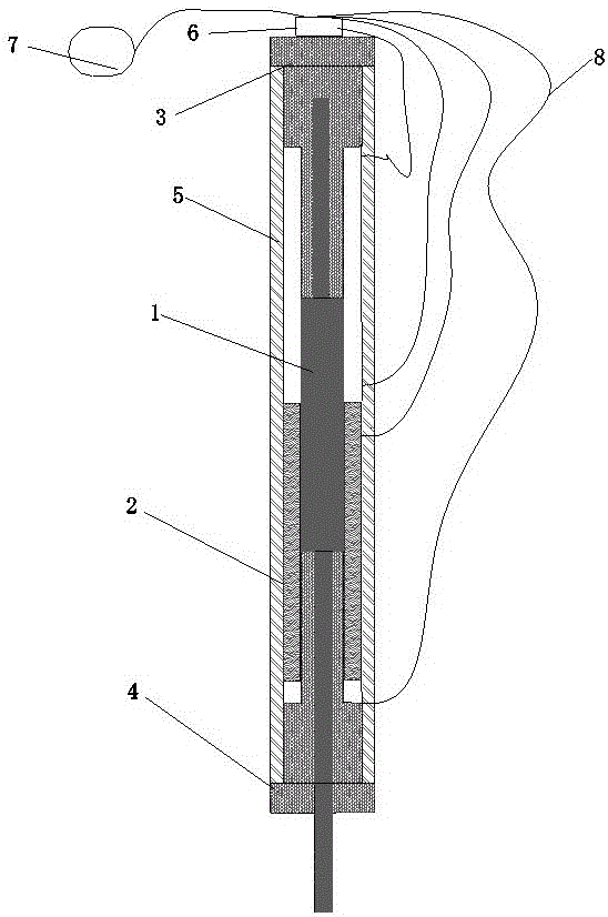
[0072] Such as figure 1 As shown, a hydrodynamic rotating device includes a rotating core 1, a water movable plug 2, an upper sealing cover 3, a lower sealing cover 4, a piston housing 5, a liquid flow switch device 6, a water pump or high-potential energy water 7, a water pipe 8.

[0073] The rotor core 1 is in the water plug 2 and can slide and rotate with each other. The upper end of the rotor core 1 is inserted into the central groove of the upper sealing cover 3 and can rotate, and the lower end of the rotor core 1 is inserted into the central hole of the lower sealing cover 4 It protrudes from the center hole of the lower sealing cover 4 and can rotate. The rotating core 1, the water movable plug 2, the upper sealing cover 3, the lower sealing cover 4 are sleeved in the piston housing 5, and the liquid flow switch device 6 is installed in On the upper sealing cover 3, a water pum...


PUM


Abstract

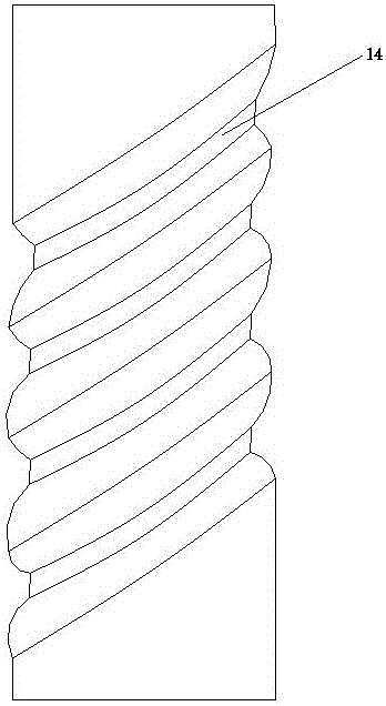
The invention belongs to the field of mechanical devices and relates to a hydrodynamic rotating device and a rotating method thereof. The hydrodynamic rotating device comprises a rotating core, a water activity plug, an upper sealing cover, a lower sealing cover, a piston shell, a liquid flow switching device, a water pump or water with high potential energy and a water pipe; the water activity plug is pushed by a hydrodynamic force generated by the water with high potential energy to vertically move; and the slip between a thread groove of the rotating core and the water activity plug results in the forward and reverse rotations of the rotating core. The hydrodynamic rotating device can widely provide power for the mechanical industry, can replace a motor to do work and can replace electric power with the hydrodynamic force, so that the working cost is reduced; or the hydrodynamic rotating device is applied to places where the motor is not adapted and no power is supplied, and particularly, the hydrodynamic rotating device replaces the electric power and the motor to take a huge effect when the condition that no electric power is provided because of natural and man-made disasters happens.

Description

Technical field [0001] The invention belongs to the field of mechanical devices, in particular to a hydrodynamic rotating device and a rotating method thereof. Background technique [0002] In the field of mechanical devices, rotating machines or components is widely used. Generally, the power used is electricity, wind, water, steam, chemical, solar, nuclear reaction energy, and so on. [0003] The most commonly used method is to use electricity to rotate machines or components through motors, gears, bearings and other components. But sometimes the motor is not adapted to some specific situations and landforms, or other energy and other forces can be used to save electricity, such as: 1. Sometimes the electricity does not reach a specific place and the motor cannot be used, such as deep mountains and oceans; 2. Sometimes It is very inconvenient to use motors in underground, underwater, and damp places; 3. In some places, high-potential energy water is very abundant, and hydrodynam...

Claims


Application Information

Patent Timeline
IPC IPC(8): F03C1/007F03C1/40
CPCF03C1/002F03C1/003F03C1/007
Inventor 郑柏林王玉章郑国荣杨京广
Owner ZHENGZHOU SHENLIDA DRILLING & PRODION EQUIP
Learn More