Intelligent soot blowing method for heat engine plant boiler

A technology for thermal power plants and boilers, which is applied in the field of intelligent soot blowing of boilers in thermal power plants. The demand degree is accurate and credible, the soot blowing strategy is reasonable and effective, and the effect of ensuring reliable operation

Active Publication Date: 2017-02-15
SHANGHAI UNIVERSITY OF ELECTRIC POWER
View PDF9 Cites 8 Cited by
  • Summary
  • Abstract
  • Description
  • Claims
  • Application Information

AI Technical Summary

Problems solved by technology

However, in the actual operation of power plants, coal types are usually mixed, and the coal quality is erratic. The unit load needs to be changed randomly to follow the AGC command of the power grid. It is difficult to obtain the actual value of the cleaning factor of the heating surface.
As a result, on-site operators cannot accurately grasp the demand for soot blowing in real time, so the existing method generally adopts the method of timing soot blowing, which makes the economical efficiency of boiler operation poor

Method used


Image

  • Intelligent soot blowing method for heat engine plant boiler
  • Intelligent soot blowing method for heat engine plant boiler

Examples


Embodiment

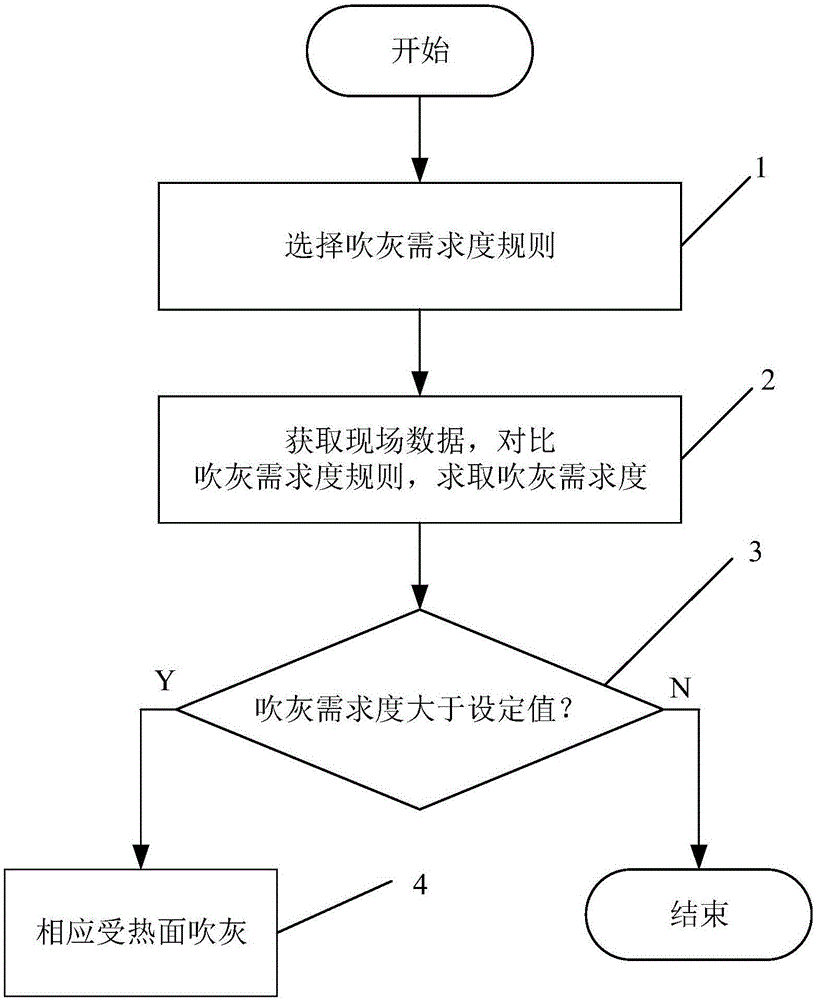
[0073] like figure 1 Shown, a thermal power plant boiler intelligent soot blowing method, the method is:

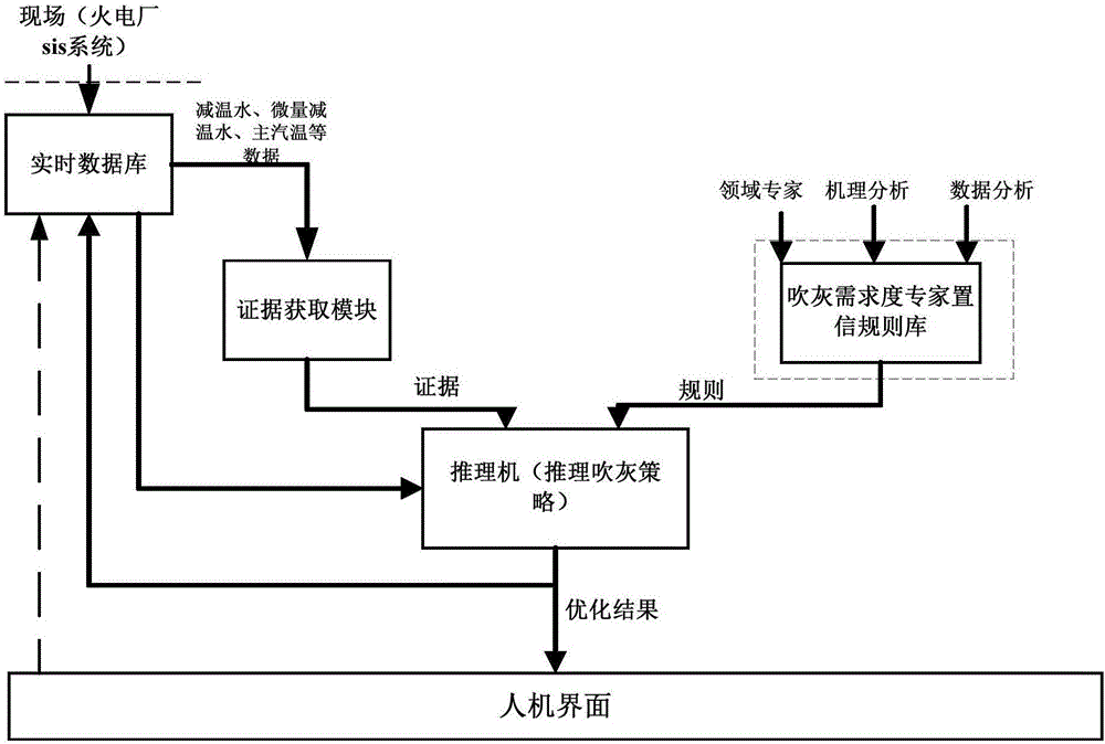
[0074] Step 1: According to the set sootblowing strategy, obtain the flue sootblowing demand degree rule and the furnace soot blowing demand degree rule respectively from the established sootblowing demand degree expert confidence rule base;

[0075] Step 2: Collect on-site boiler operation data and compare it with the rule parameters in the flue sootblowing demand degree rule and the furnace sootblowing demand degree rule, and then obtain the soot blowing demand degree of the flue and furnace heating surface;

[0076] Step 3: Determine whether the demand degree of sootblowing is greater than the set demand degree value, and the set demand degree value is 0.7. If so, perform step 4, otherwise end;

[0077] Step 4: Perform soot blowing on the corresponding heating surface in the rules according to the corresponding soot blowing requirements.

[0078] The soot blowing str...


PUM


Abstract

The invention relates to an intelligent soot blowing method for a heat engine plant boiler. The intelligent soot blowing method includes the steps that, (1) according to a set soot blowing strategy, a flue soot blowing demand degree rule and a hearth soot blowing demand degree rule are respectively obtained from an established soot blowing degree expert confidence rule base; and (2) operating data of an on-site boiler are obtained, and compared with rule parameters of the flue soot blowing demand degree rule and the hearth soot blowing demand degree rule, further heating surface soot blowing demand degrees of a flue and a hearth are obtained, and a heating surface corresponding to the soot blowing demand degree rule is subjected to soot blowing when the soot blowing demand degree is bigger than a set demand degree. Compared with the prior art, existing timing soot blowing is changed into soot blowing as required through using the intelligent soot blowing method for the heat engine plant boiler, and the heat absorbing distribution conditions of the heating surfaces at all levels are changed; and the heat absorbing proportion of the heating surfaces at all levels is redistributed to maintain the stabilization of temperature, the utilization of micro-attemperation water is reduced and economy is improved.

Description

technical field [0001] The invention relates to a soot blowing method, in particular to an intelligent soot blowing method for a thermal power plant boiler. Background technique [0002] During the pulverized coal combustion process of coal-fired power plant boilers, ash slagging on the heating area is an inevitable problem, and soot blowing is the main way to solve the problem of ash slagging on the heating area. The current optimization method for boiler soot blowing is mainly based on the theoretical basis for calculating the cleaning factor of the heating surface. However, in the actual operation of power plants, coal types are usually mixed, and the coal quality is erratic. The load of the unit needs to be changed randomly to follow the AGC command of the power grid. It is difficult to obtain the actual value of the cleaning factor of the heating surface. As a result, on-site operators cannot accurately grasp the demand for soot blowing in real time, so the existing me...

Claims


Application Information

Patent Timeline
Patent Type & Authority Applications(China)
IPC IPC(8): F23J3/02
CPCF23J3/023F23J3/026
Inventor 钱虹张栋良王啸宋亮陈琪琪
Owner SHANGHAI UNIVERSITY OF ELECTRIC POWER
Why Eureka
Try Eureka