Infrared scanning temperature measurement correction method

An infrared and scanner technology, applied in the field of infrared scanning temperature measurement and correction, can solve problems such as inaccurate temperature and achieve the effect of improving accuracy

Active Publication Date: 2018-10-16
HEFEI GOLD STAR MECHATRONICS TECH DEV CO LTD
View PDF8 Cites 0 Cited by
  • Summary
  • Abstract
  • Description
  • Claims
  • Application Information

AI Technical Summary

Problems solved by technology

[0004] The purpose of the present invention is to provide a correction method for infrared scanning temperature measurement to solve the problem of inaccurate temperature measured by existing infrared scanners

Method used


Image

  • Infrared scanning temperature measurement correction method
  • Infrared scanning temperature measurement correction method
  • Infrared scanning temperature measurement correction method

Examples


Embodiment Construction

[0020] Combine below Figure 1 to Figure 8 , the present invention is described in further detail.

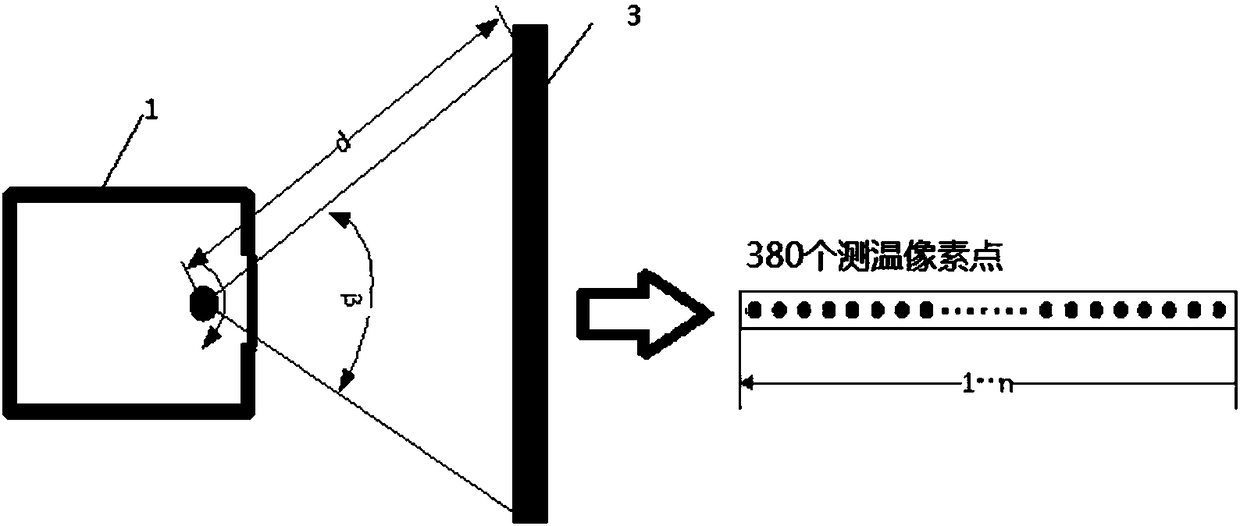
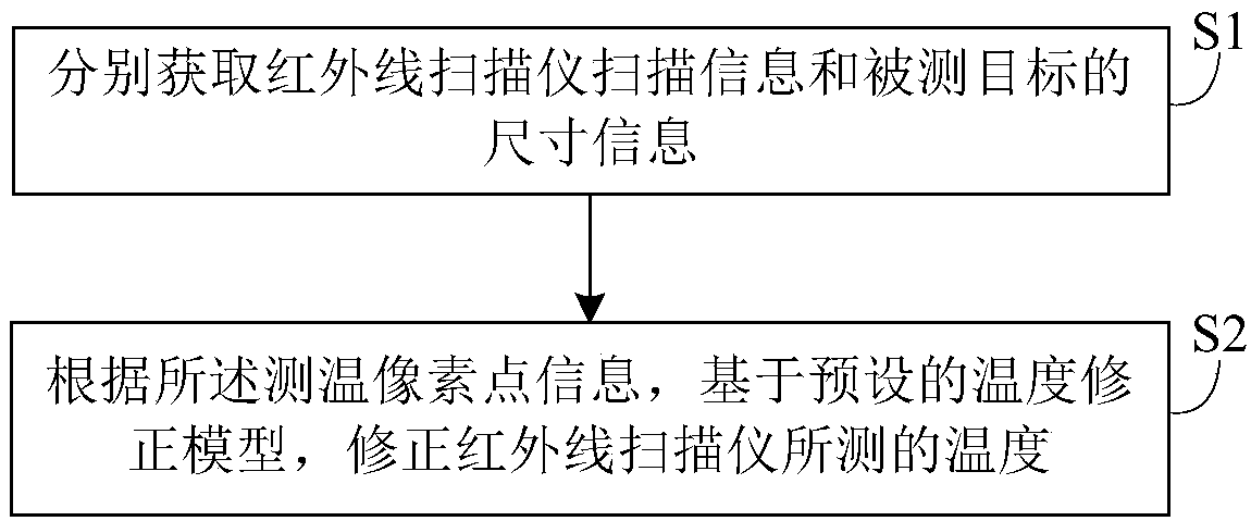
[0021] Such as figure 1 As shown, this embodiment discloses a temperature measurement correction method of an infrared scanner, including the following steps S1 to S2:

[0022] S1. Respectively acquire the scanning information of the infrared scanner and the size information of the measured target, the scanning information of the infrared scanner includes the temperature measurement pixel point information of the scanning field of view and the installation position information of the infrared scanner relative to the measured target;

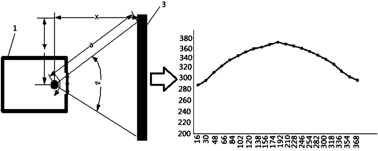
[0023] S2. Correct the temperature measured by the infrared scanner based on the temperature measurement pixel point information and based on the preset temperature correction model;

[0024] Wherein, the temperature correction model is:

[0025]

[0026] Among them, A, x c 、y 0 、w 1 、w 2 、w 3 , b is a constant, β is the range of the in...


PUM


Abstract

The invention discloses an infrared scanning temperature measurement and correction method, which belongs to the technical field of infrared thermal image temperature measurement. The established temperature correction model corrects the temperature measured by the infrared scanner. Through the preset temperature correction model, the temperature of each temperature measurement pixel in the scanning field of view of the infrared scanner is corrected, and the influence of the angle and distance of the window on the temperature measured by the infrared scanner is corrected, so that the temperature measured by the infrared scanner is more accurate. Accurately close to the temperature of the measured target, which improves the accuracy of the temperature measured by the infrared scanner.

Description

technical field [0001] The invention relates to the technical field of infrared thermal imaging temperature measurement, in particular to an infrared scanning temperature measurement correction method. Background technique [0002] In order to carry out scientific operation and management of the coking heating furnace, it is necessary to monitor the temperature field distribution on the surface of the furnace tube in real time, accurately determine the surface temperature of the furnace tube at any point in the side furnace, and analyze the change of the temperature rise and temperature difference on the surface of the furnace tube. Judging the trend of coking inside the furnace tube and the state of coking, and giving early warning of high temperature and low temperature exceeding the limit of the furnace tube within the visible field. [0003] Nowadays, infrared temperature measurement technology is generally used to monitor the temperature field distribution on the surfac...

Claims


Application Information

Patent Timeline
Patent Type & Authority Patents(China)
IPC IPC(8): G01J5/00
CPCG01J5/00G01J5/80
Inventor 曹明润张亚东张卫星徐勇汪升
Owner HEFEI GOLD STAR MECHATRONICS TECH DEV CO LTD
Why Eureka
Try Eureka