Supercharge Your Innovation With Domain-Expert AI Agents!

A clipping wall plate device for transonic test section

A test section and panel technology, applied in measuring devices, aerodynamic tests, machine/structural component testing, etc., can solve problems such as low precision of the staggered panels, inability to adjust, and influence of panel noise on the flow field, etc., to achieve The effect of high system accuracy

Active Publication Date: 2018-09-07
AVIC SHENYANG AERODYNAMICS RES INST
View PDF4 Cites 0 Cited by
  • Summary
  • Abstract
  • Description
  • Claims
  • Application Information

AI Technical Summary

Problems solved by technology

The initial method was realized by replacing the wall panels. Later, there was a double-layer wall panel design. Holes are opened on the panel, and the panel contacting the flow field does not move. The outer panel shifts to change the ventilation area of ​​the hole, thereby Change the air permeability of the whole wall panel, but change it together, and cannot adjust it separately according to each section of the flow field
Moreover, there is cross-flow in the existing structure, the noise generated by the wall plate affects the flow field, and the movement accuracy of the staggered plate is low

Method used


Image

  • A clipping wall plate device for transonic test section
  • A clipping wall plate device for transonic test section
  • A clipping wall plate device for transonic test section

Examples


Embodiment 1

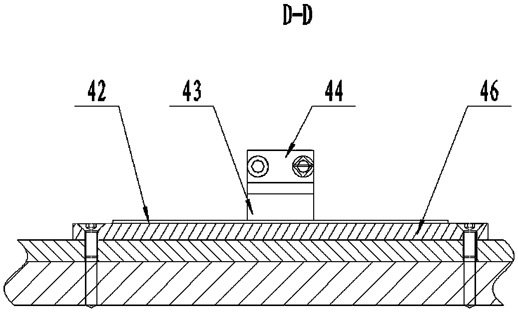
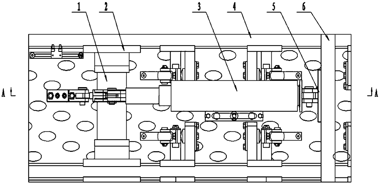
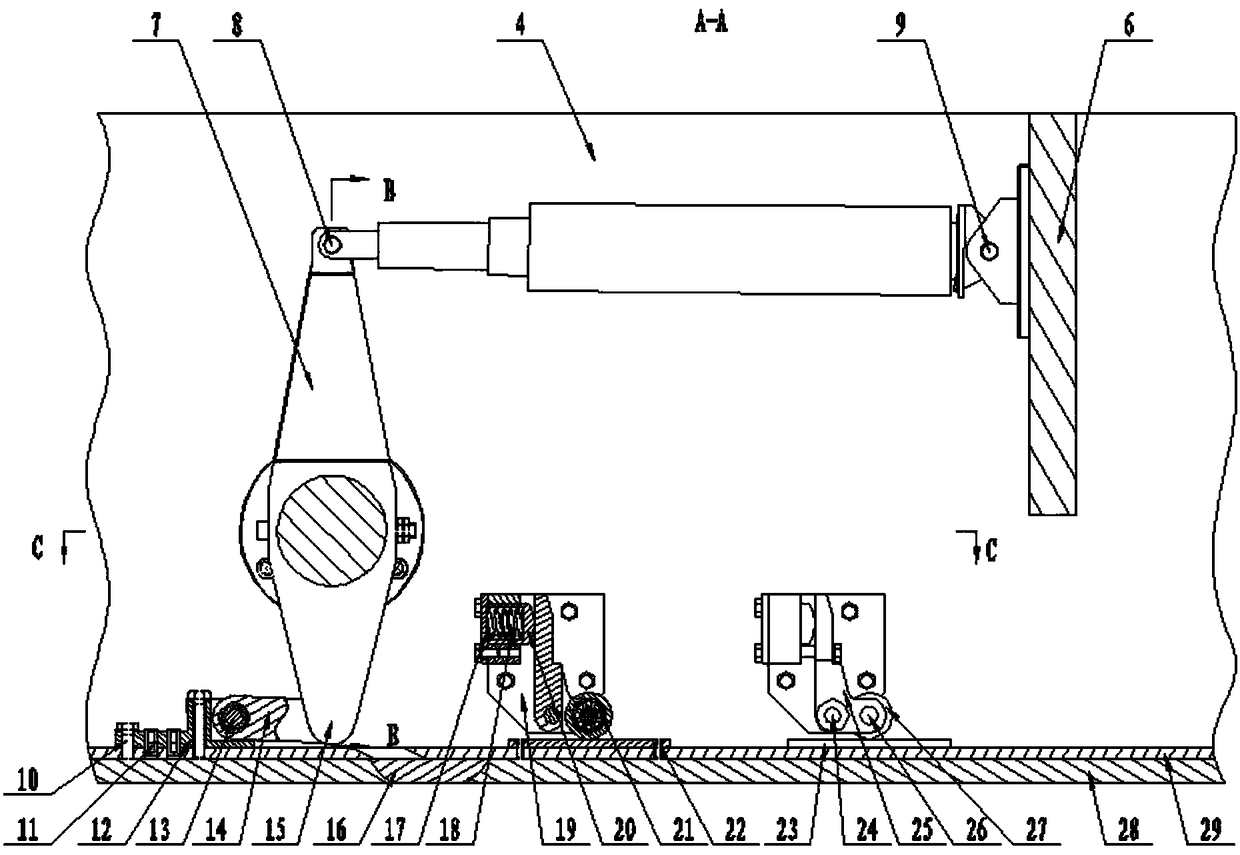
[0021] See attached Figure 1-6 As shown, a clipping panel device in the test section includes a panel frame, an inner layer plate 28, a shifting plate 29, a driving mechanism, a position feedback system for the shifting plate, a pressing mechanism and a guiding mechanism; the panel frame Including longitudinal rib 4 and transverse rib 6, the surface of longitudinal rib 4 is higher than the surface of transverse rib 6, longitudinal rib 4 and transverse rib 6 are connected by welding; the drive mechanism includes support shaft 1, flange 2, electric cylinder 3, ear seat 5, swing arm 7, tie rod seat 12 and tie rod 14; the ear seat 5 is fixedly connected to the transverse rib 6 of the panel frame, the electric cylinder 3 is internally integrated with a servo motor, and the front end of the electric cylinder 3 is hinged to the pendulum through the first pin shaft 8 On the arm 7, the rear end of the electric cylinder 3 is hinged on the lug 5 through the second pin shaft 9, the lower...

Embodiment 2

[0028] Working process and principle of the present invention are:

[0029] After the wind tunnel test starts, the airflow flows through the test section, and there will be a certain pressure difference inside and outside the test section. When the force generated by the pressure difference is enough to push the staggered plate 29 away from the inner plate 28, a group of evenly distributed pressing mechanisms The force generated by the pressure difference is offset, and the two-layer board remains in a state of bonding throughout the test. When the holes of the inner layer plate 28 and the shifting plate 29 are all or partly communicated, part of the air flow enters the chamber through the holes on the wall plate, and the thin metal sheet provided in the inner layer plate 28 holes reduces the noise of the air flow. According to the test requirements, control the rotation of the swing arm of the driving mechanism in the corresponding area, pull the rod seat 12 and the shift pla...


PUM


Abstract

The invention provides a clipping wallboard device for a transonic-speed test section. The clipping wallboard device comprises a wallboard frame, an inner board with a thin metal piece embedded, a slip board, a drive mechanism, a servo control system, a slip board position feedback system, a compression structure, and a guiding structure. The inner board is fixed on a longitudinal rib of the frame; the slip board is pasted on the inner board and is spaced from a horizontal rib of the frame at a certain interval. An electric cylinder in the drive mechanism pushes an oscillating arm to rotate around a support shaft; and the support shaft pulls a pull rod seat and the slip board to move by a pull rod. The slip board drives a grating ruler to move and thus the grating ruler and a reading head fixed on the longitudinal rib move relatively, thereby feeding back displacement of the slip board precisely. With the device, the location of the slip board can be controlled accurately and the venting areas of different regions can be controlled accurately, thereby adjusting a flow field inside a test section accurately to adapt to tests of different Ma numbers and different models.

Description

technical field [0001] The invention relates to wind tunnel test equipment, in particular to a clipping panel device for a transonic test section. Background technique [0002] In the transonic wind tunnel, the test section is a half-open and half-closed ventilating wall, with a resident room outside, and part of the flow in the test section enters the resident room. The purpose is to solve several problems in the generation of transonic flow: wind tunnel blockage, uniform Low supersonic flow, reduce or eliminate subsonic wall interference, reduce or eliminate the impact of shock wave reflection. After testing and research, if the test section adopts perforated or slotted ventilating wall panels, and the opening is appropriate, these four problems can be solved. However, different tests require different openings or slots, which requires changing the air permeability of the wall panels for different tests. The initial method was realized by replacing the wall panels. Later...

Claims


Application Information

Patent Timeline
Patent Type & Authority Patents(China)
IPC IPC(8): G01M9/04
CPCG01M9/04
Inventor 赵文涛刘广宇赵林成崔晓春高琦刘畅刘海涵
Owner AVIC SHENYANG AERODYNAMICS RES INST
Features
  • R&D
  • Intellectual Property
  • Life Sciences
  • Materials
  • Tech Scout
  • Unparalleled Data Quality
  • Higher Quality Content
  • 60% Fewer Hallucinations
Learn More