Keyboard
A keyboard and key technology, applied in the field of electronic products, can solve problems such as single structure
- Summary
- Abstract
- Description
- Claims
- Application Information
AI Technical Summary
Problems solved by technology
Method used
Image
Examples
Embodiment 1
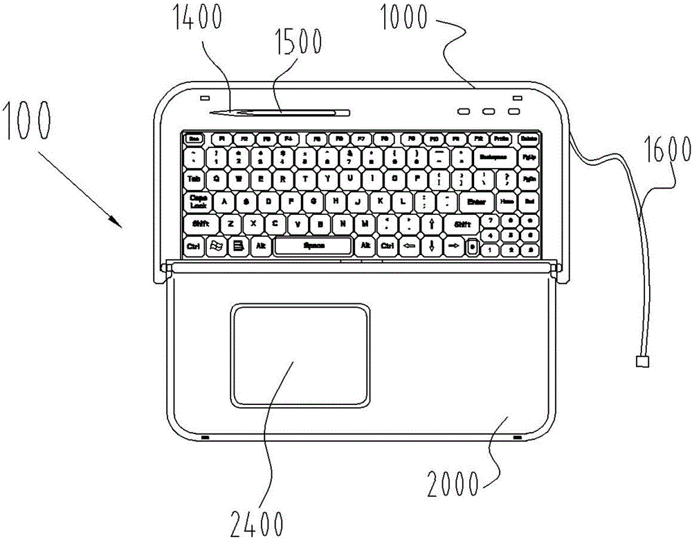
[0066] refer to figure 1 , the present invention proposes a keyboard 100 , including a main body 1000 provided with keys, and the main body 1000 is connected with a sliding cover 2000 .
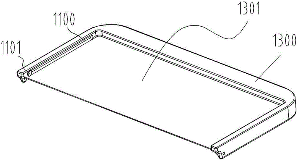
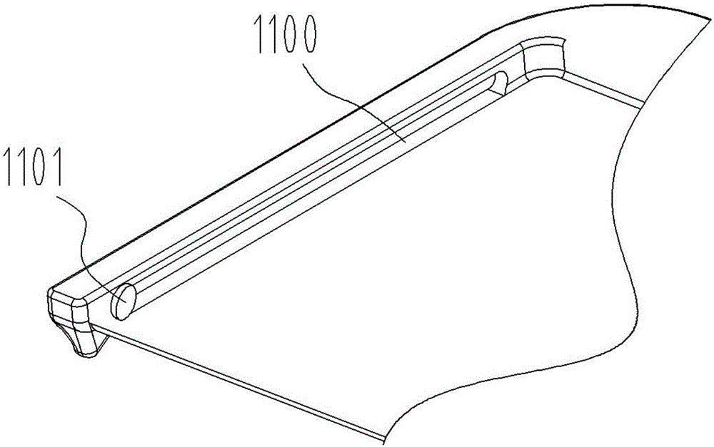
[0067] Such as figure 2 As shown, the main body 1000 is provided with a sliding slot 1100 .
[0068] Such as image 3 As shown, the sliding cover 2000 is provided with a connecting shaft 2100 .
[0069] The connecting shaft 2100 is slidably connected with the chute 1100 .
[0070] Such as Figure 3a As shown, the connecting shaft 2100 is a cylindrical structure.
[0071]The connecting shaft 2100 is arranged on both sides of the sliding cover 2000 , and the structure of the connecting shaft 2100 matches the structure of the sliding groove 1100 .
[0072] Such as figure 2 As shown, the chute 1100 includes a terminal end 1101 .
[0073] The connecting shaft 2100 is rotatably connected with the terminal end 1101 .
[0074] Such as Figure 2a As shown, the cross section of the terminal...
Embodiment 2
[0099] refer to Figure 7 , the present invention proposes a keyboard 100 , including a main body 1000 provided with keys, and the main body 1000 is connected with a sliding cover 2000 .
[0100] Such as figure 2 As shown, the main body 1000 is provided with a sliding slot 1100 .
[0101] Such as image 3 As shown, the sliding cover 2000 is provided with a connecting shaft 2100 .
[0102] The connecting shaft 2100 is slidably connected with the chute 1100 .
[0103] Such as Figure 3a As shown, the connecting shaft 2100 is a cylindrical structure.
[0104] The connecting shaft 2100 is arranged on both sides of the sliding cover 2000 , and the structure of the connecting shaft 2100 matches the structure of the sliding groove 1100 .
[0105] Such as figure 2 As shown, the chute 1100 includes a terminal end 1101 .
[0106] The connecting shaft 2100 is rotatably connected with the terminal end 1101 .
[0107] Such as Figure 2a As shown, the cross section of the termin...
Embodiment 3
[0130] refer to Figure 8 , the present invention proposes a keyboard 100 , including a main body 1000 provided with keys, and the main body 1000 is connected with a sliding cover 2000 .
[0131] Such as figure 2As shown, the main body 1000 is provided with a sliding slot 1100 .
[0132] Such as image 3 As shown, the sliding cover 2000 is provided with a connecting shaft 2100 .
[0133] The connecting shaft 2100 is slidably connected with the chute 1100 .
[0134] Such as Figure 3a As shown, the connecting shaft 2100 is a cylindrical structure.
[0135] The connecting shaft 2100 is arranged on both sides of the sliding cover 2000 , and the structure of the connecting shaft 2100 matches the structure of the sliding groove 1100 .
[0136] Such as figure 2 As shown, the chute 1100 includes a terminal end 1101 .
[0137] The connecting shaft 2100 is rotatably connected with the terminal end 1101 .
[0138] Such as Figure 2a As shown, the cross section of the termina...
PUM
 Abstract
Description
Claims
Application Information
 - R&D
- Intellectual Property
- Life Sciences
- Materials
- Tech Scout
- Unparalleled Data Quality
- Higher Quality Content
- 60% Fewer Hallucinations
Browse by: Latest US Patents, China's latest patents, Technical Efficacy Thesaurus, Application Domain, Technology Topic, Popular Technical Reports.
© 2025 PatSnap. All rights reserved.Legal|Privacy policy|Modern Slavery Act Transparency Statement|Sitemap|About US| Contact US: help@patsnap.com


