LED backlight control method

A technology of LED backlight and backlight control, which is applied in the direction of instruments and static indicators, etc., which can solve the problems of being unable to control LED lights individually, unable to control LED lights, and unable to control accurately, so as to achieve easy mass production, easy expansion, Effects that are easy to implement

Inactive Publication Date: 2017-02-15
SHENZHEN KANG MING SHENG TECH IND INC CO
View PDF4 Cites 1 Cited by
  • Summary
  • Abstract
  • Description
  • Claims
  • Application Information

AI Technical Summary

Problems solved by technology

[0002] LED backlight modules generally include multiple LED lamps, which are either arranged on the side or on the front in an array. Due to the limited port resources of the controller, the existing solution is to divide multiple LED lamps into multiple groups. , each group is controlled separately, the control effect of this control method is poor, because one of the LED lights cannot be controlled individually, or any number of LED lights can not be controlled, the flexibility is poor in practical applications, and, because of the inability to precisely control , so the energy saving effect is poor
[0003] In addition, in the existing solutions, a dedicated dimming solution is generally designed based on specific applications, and the scalability is poor.

Method used


Image

  • LED backlight control method
  • LED backlight control method
  • LED backlight control method

Examples


Embodiment 1

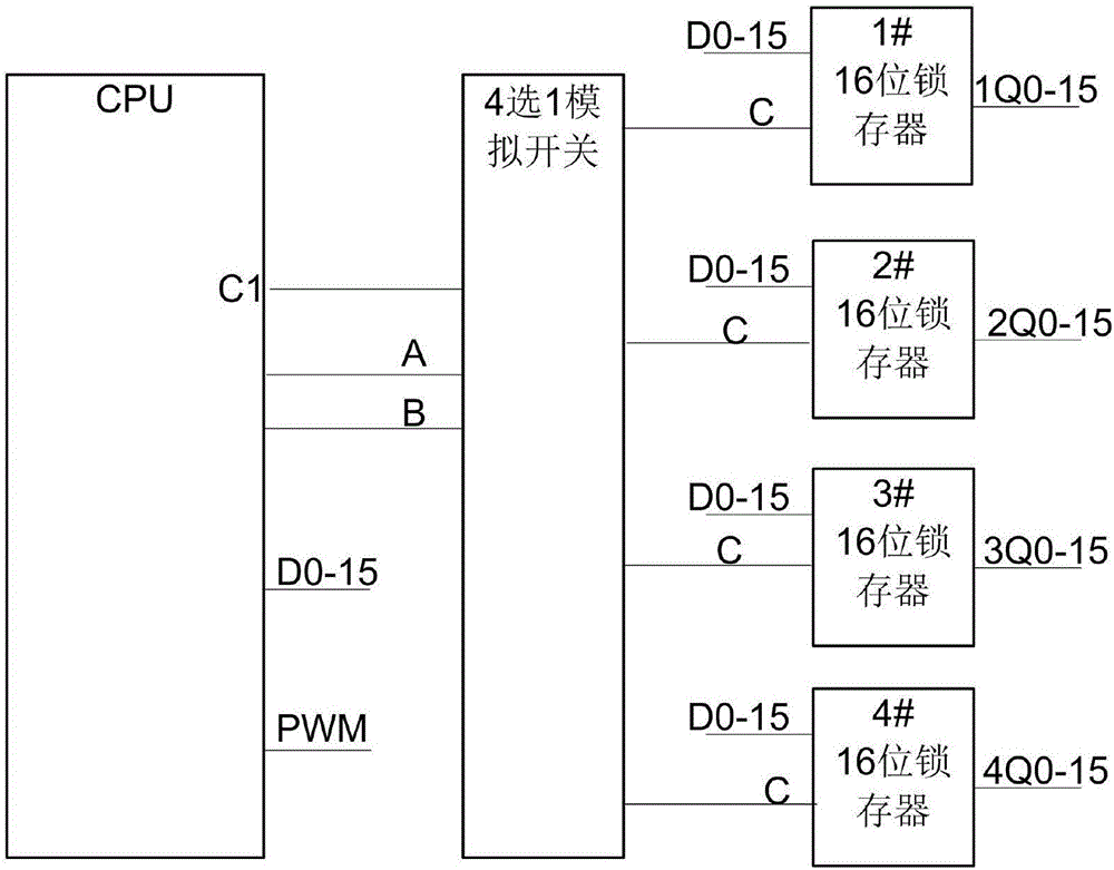
[0085] Embodiment 1: as Figures 1 to 4 , a kind of LED backlight control method, controls LED backlight; LED backlight comprises LED light-emitting array, CPU, dimming module, multi-channel analog switch and M latches; Multi-channel switch is M selects 1 analog switch; The number of channels of the multi-way switch and the number of latches are both M; M is a natural number;

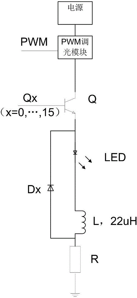
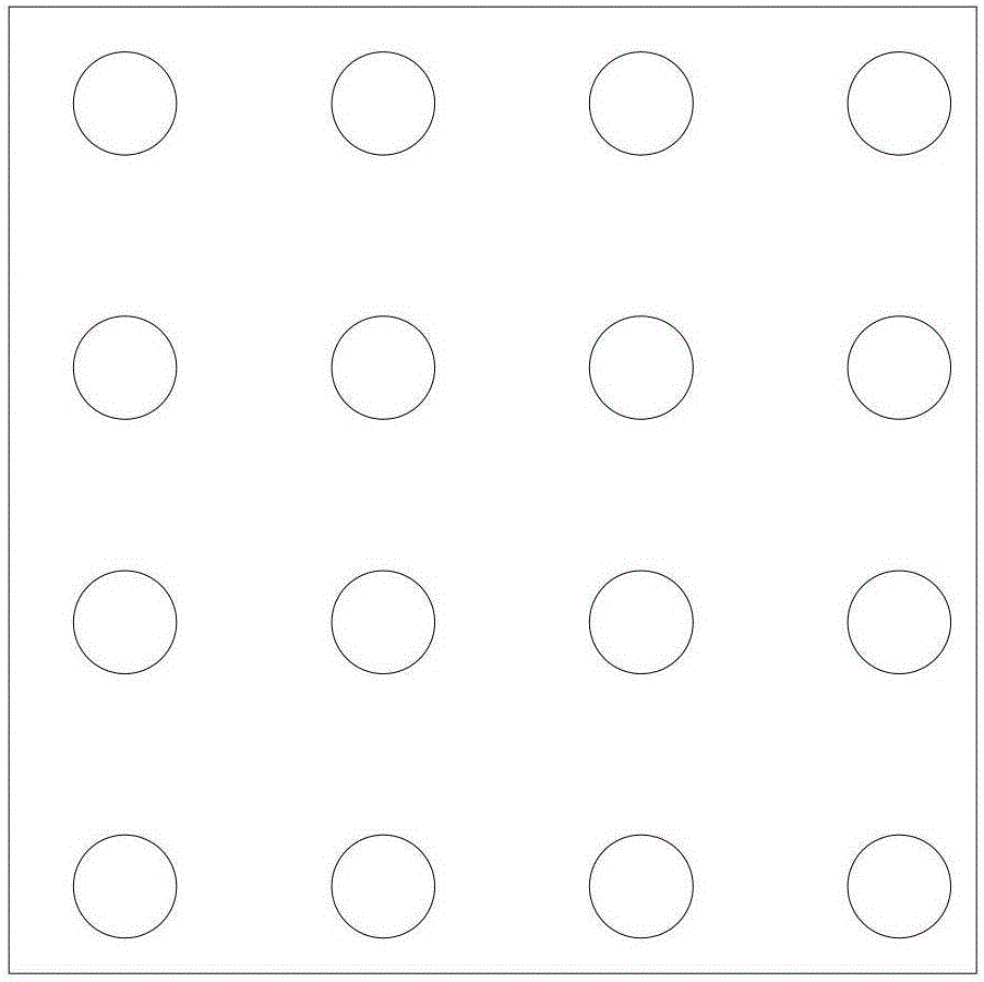
[0086] The LED light-emitting array includes M*N LED light-emitting modules connected in parallel; the dimming module is connected to the power supply; multiple LED light-emitting modules are connected to the output end of the dimming module; M*N LED light-emitting modules are divided into M groups, and each group Including N LED lighting modules;

[0087] The dimming module is controlled by the CPU, and the CPU controls the output voltage or output current of the dimming module through the dimming module;

[0088] The CPU, multi-channel analog switches, latches and LED light-emitting arrays are conne...

Embodiment 2

[0106] Embodiment 2: On the basis of Embodiment 1, the LED lighting module is further improved:

[0107] Such as Figure 5-13 , the LED lighting module includes 2 LED lamps and the plug body 12; the circuit board is provided with a socket 3; the socket is provided with a jack 7 for inserting the plug body; the bottom of the jack is provided with a socket for supplying power to the plug-in light emitting module Contact 9; the plug is provided with a plug contact 4 for contacting with the socket contact;

[0108] The LED lighting module has a petal-shaped lampshade, and the petal-shaped lampshade is formed by butting four single petals 6; one end of the four single petals is connected to form the lamp bowl of the petal-shaped lampshade, and the other end of the four single petals forms the outstretched part of the lampshade. The LED light-emitting module is located at the bottom of the lamp bowl; the bottom of the lamp bowl is a plane, which is the light-emitting surface of the...

Embodiment 3

[0117] Embodiment 3: On the basis of Embodiment 1, the connection structure of the LED lighting module is further improved: as Figure 14-16 , the LED lighting module includes an LED lamp and a cylindrical insert 12;

[0118] The insert body is provided with a positive pole insert 61 and a negative pole insert 62; the outer sides of the positive pole insert and the negative pole insert are respectively provided with a recessed part with a slope; the two recesses are located at the front ends of the positive pole insert and the negative pole insert ; The positive static contact 41 and the negative static contact 42 are respectively provided in the two depressions; the circuit board is provided with a socket adapted to the plug; the socket has a jack for accommodating the plug; The positive slot and the negative slot corresponding to the positive strip and the negative strip;

[0119] In order to avoid reverse connection of positive and negative poles, the width of the positive...


PUM


Abstract

The invention discloses an LED backlight control method for controlling an LED backlight source. The method comprises: step one, carrying out initialization; step two, display parameter data are loaded to an LED light-emitting array; and step three, whether the display parameter data change; if not, waiting is carried out continuously; and if so, a changed data assignment value is provided for the data and the step two is carried out. Therefore, controlling of one or more light-emitting modules is realized based on limited port resources and thus the method is easy to implement.

Description

technical field [0001] The invention relates to an LED backlight control method. Background technique [0002] LED backlight modules generally include multiple LED lamps, which are either arranged on the side or on the front in an array. Due to the limited port resources of the controller, the existing solution is to divide multiple LED lamps into multiple groups. , each group is controlled separately, the control effect of this control method is poor, because one of the LED lights cannot be controlled individually, or any number of LED lights can not be controlled, the flexibility is poor in practical applications, and, because of the inability to precisely control , so the energy saving effect is poor. [0003] In addition, in the existing solutions, a dedicated dimming solution is generally designed based on a specific application, and the scalability is poor. [0004] Therefore, it is necessary to design a new LED backlight control method. Contents of the invention ...

Claims


Application Information

Patent Timeline
Patent Type & Authority Applications(China)
IPC IPC(8): G09G3/32
CPCG09G3/32
Inventor 李迪初聂卫陶正佳
Owner SHENZHEN KANG MING SHENG TECH IND INC CO
Why Eureka
Try Eureka