

Power bank device
A mobile power supply and power device technology, which is applied to circuit devices, battery circuit devices, circuits, etc., can solve the problems of consuming a large amount of built-in power in mobile phones, consuming a large amount of power, and easily igniting batteries, so that the power can be expanded and recharged at will. High discharge efficiency and the effect of increasing the discharge capacity
- Summary
- Abstract
- Description
- Claims
- Application Information
AI Technical Summary
Problems solved by technology
Method used
Image

Examples
Embodiment 1
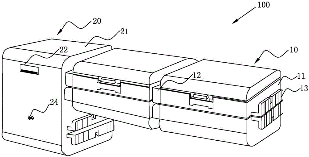
[0032] figure 1 It is a schematic structural diagram of the mobile power supply device in Embodiment 1 of the present invention.
[0033] Such as figure 1 As shown, in this embodiment, the mobile power supply device 100 can directly use the battery to discharge the electric device, which is especially suitable for travelers in the field. By increasing the number of batteries to adjust the power of the mobile power supply device 100, thereby realizing Effective charging of mobile phones, cameras, tablets, etc. In addition, the battery can be charged quickly using an external power source.
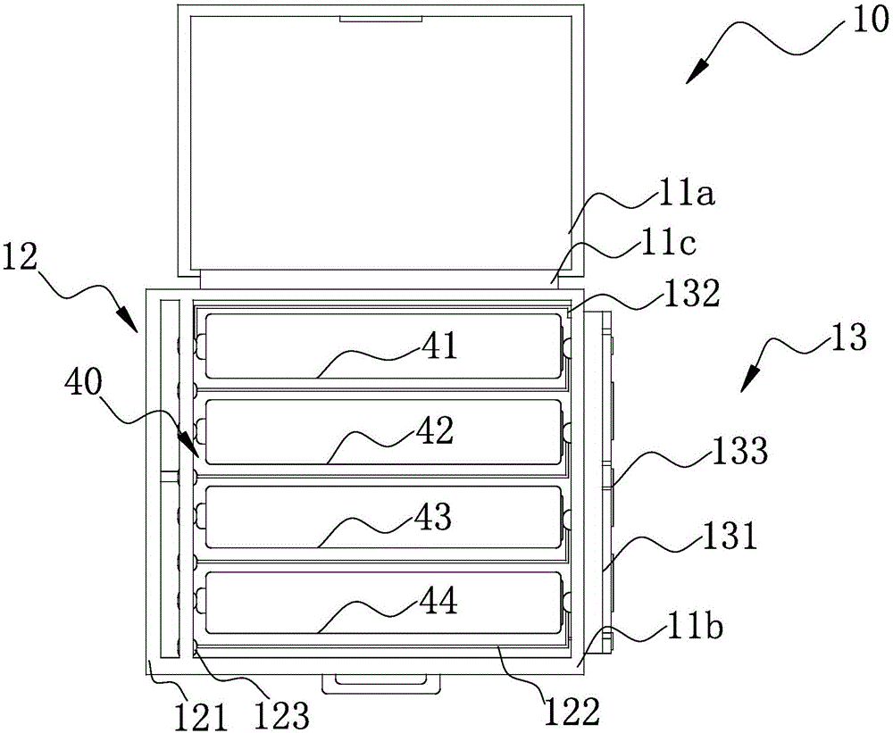
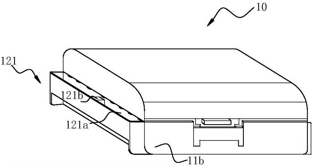
[0034] The mobile power supply device 100 includes: four battery packs 10 and a charging and discharging unit 20 .
[0035] The battery pack 10 includes a battery compartment 11 , a battery-side connecting unit 12 and a stacking connecting unit 13 . The battery side connecting unit 12 is arranged on one side of the battery compartment 11, and the superposition connecting unit 13 is arran...
Embodiment 2
[0066] In this second embodiment, for the same structures as those in the first embodiment, the same symbols are used and the same descriptions are omitted.
[0067] Figure 7 It is a structural schematic diagram of the mobile power supply device in the second embodiment of the present invention.
[0068] Such as Figure 7 As shown, the mobile power supply device 200 includes: four battery packs 10 , a charging and discharging unit 210 and a control unit (not shown in the figure).
[0069] The charging and discharging unit 210 includes: a main body 211 , an output unit 212 , an input unit 213 and a charging and discharging side connection unit (not shown in the figure).
[0070] The main body 211 is a rectangular parallelepiped with six sidewalls, and the output unit 212 and the input unit 213 are arranged on the front sidewall of the main body 211 . The charging and discharging side connecting unit is arranged on a side wall of the main body 211, from Figure 8 Seen from ...
PUM
 Abstract
Description
Claims
Application Information