High Discharge Capacity Lithium Battery

Active Publication Date: 2010-06-17
ENERGIZER BRANDS
View PDF57 Cites 18 Cited by
  • Summary
  • Abstract
  • Description
  • Claims
  • Application Information

AI Technical Summary

Benefits of technology

[0014]In view of the above, an object of the present invention is to provide a lithium battery cell with increased discharge capacity. Another object of the invention is to provide a lithium battery cell with a high energy density (interfacial discharge capacity to interfacial electrode volume). Another object of the invention is to provide a Li/FeS2 cell with a high interfacial electrode surface area that

Problems solved by technology

However, there will always be practical limitations on the maximum internal volume.
This often means using designs containing less active materials, thus sacrificing capacity on low power and low rate discharge.
For batteries that are intended for both high and low power use, reducing cell active material inputs in order to maximize high power performance is less desirable than for batteries intended for only high power use.
There are practical limitations to doing so.
However, changes made to increase strength can also adversely affect separator performance, based in part on factors such as cell chemistry, electrode design and features, cell manufacturing process, intended cell use, anticipated storage and use conditions, etc.
For certain cell chemistries maximizing the amounts of active materials in the cell can be more difficult.
These forces can cause bulging of the cell housing and short circuits through the separator.
Possible solutions to these problems include using strong (often thicker) materials for the ce

Method used


Image

  • High Discharge Capacity Lithium Battery
  • High Discharge Capacity Lithium Battery
  • High Discharge Capacity Lithium Battery

Examples


Example

Example 1

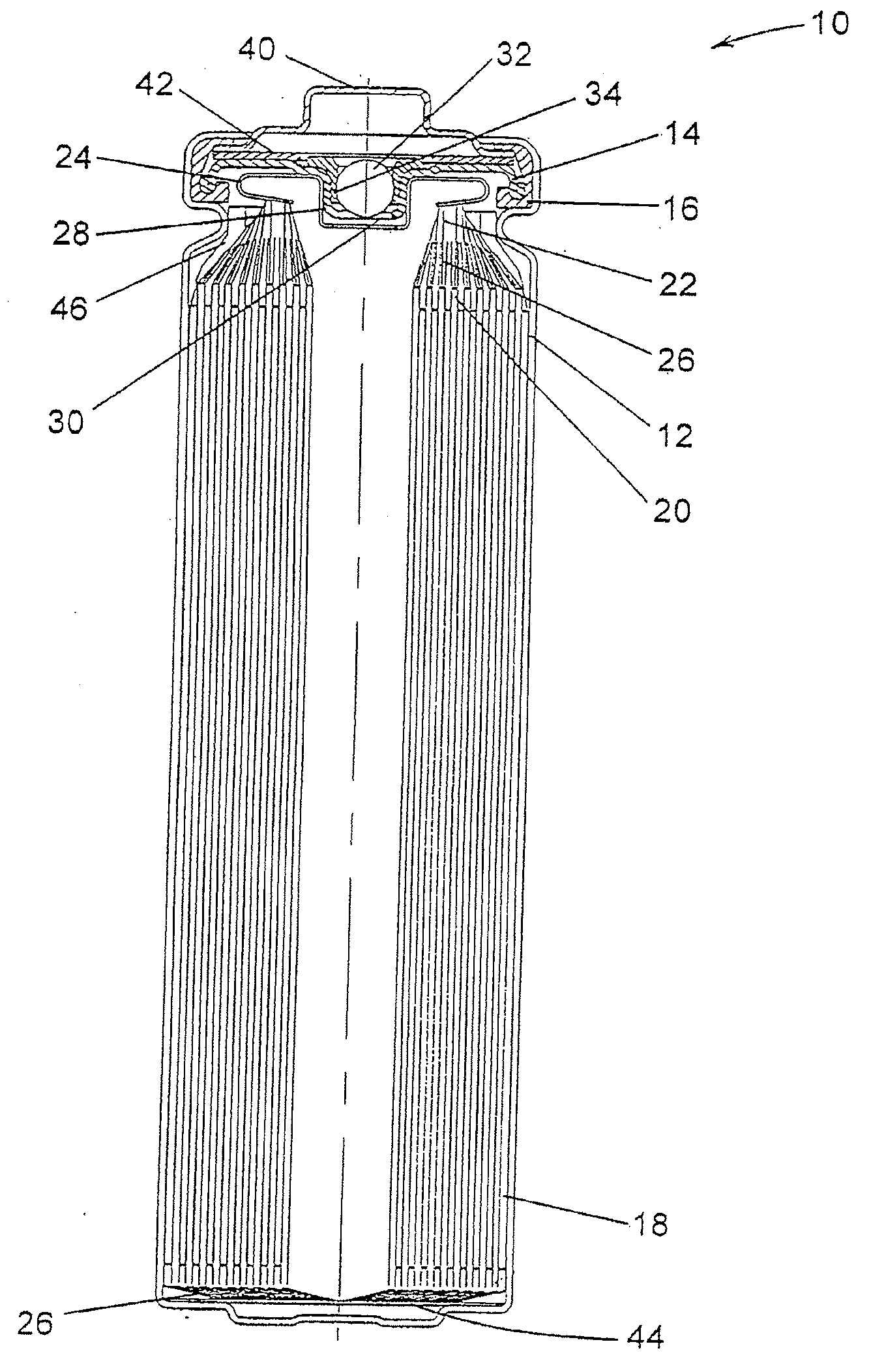
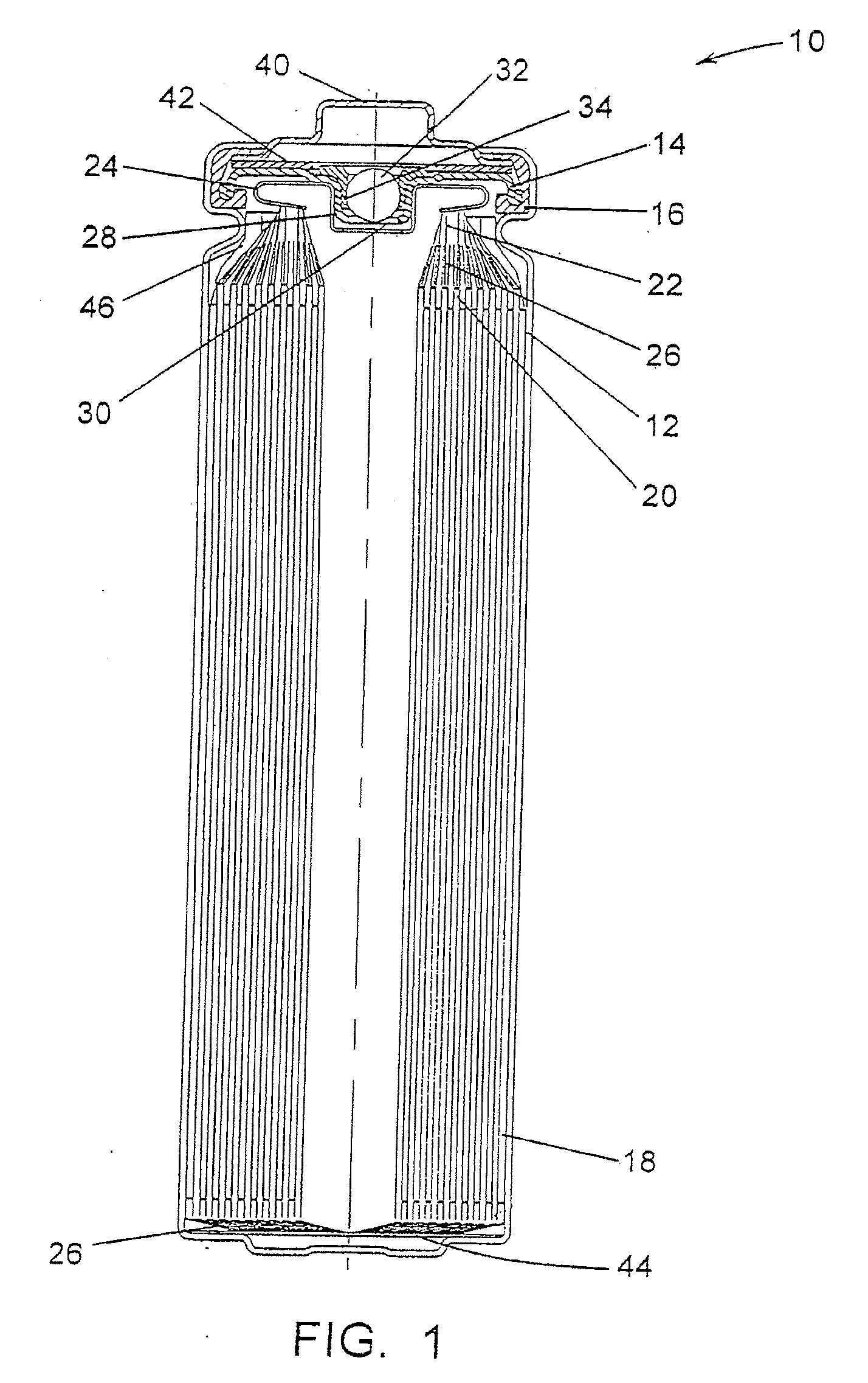
[0105]FR6 type cylindrical Li / FeS2 cells with spirally wound electrode assemblies were made with varying electrode assembly void volumes per centimeter of interfacial electrode assembly height over a range of about 0.373 to about 0.455 cm3 / cm. The void volumes were varied by adjusting the volume of the voids within the active material mixture coated on the cathode. This was done with various combinations of mixture formulations, thickness and packing. The separator material used in all cells was a highly crystalline, unixially oriented, microporous polypropylene material with a 25 μm nominal thickness.

Example

Example 2

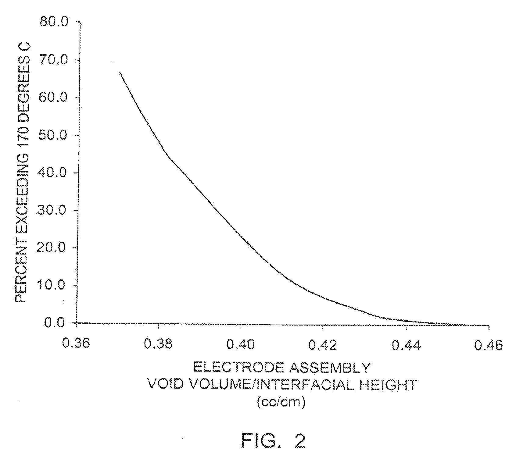
[0106]Samples of the cells from Example 1 were prepared for testing. For each group with a given void volume per unit of height, some cells remained undischarged and some cells were 50% discharged (discharged at a rate of 200 mA for the time required to remove 50 percent of the rated capacity). Undischarged and 50% discharged cells were tested on an Impact Test, and the external temperature of each of the cells tested was monitored during and for six hours after testing.

[0107]For the Impact Test a sample cell is placed on a flat surface, a 15.8 mm diameter bar is placed across the center of the sample, and a 9.1 kg mass is dropped from a height of 61±2.5 cm onto the sample. The sample cell is impacted with its longitudinal axis parallel to the flat surface and perpendicular to the longitudinal axis of the 15.8 mm diameter bar lying across the center of the cell. Each sample is subjected to only a single impact.

[0108]None of the undischarged cells had an external temperature...

Example

Example 3

[0111]Four lots of FR6 cells were made, each with a separator made from a different material. A description of the separator materials is provided in Table 1, and typical separator properties, as determined by the methods described below, are summarized in Table 2. The separator material used for Lot A is the same as that used in the cells in Example 1. Each cell contained about 1.60 g of electrolyte, the electrolyte consisting of 9.14 weight percent Lil salt in a solvent blend of 1,3-dioxolane, 1,2-dimethoxyethane and 3,5-dimethylisoxazole (63.05:27.63:0.18 by weight).

TABLE 1Lot ALot BLot CLot Dhighly crystallinehighly crystallineamorphous biaxiallyamorphous biaxiallyuniaxially orienteduniaxially orientedoriented microporousoriented microporousmicroporousmicroporousultrahigh molecularpolyethylenepolypropylenepolypropyleneweight polyethylene20 μm thick25 μm thick20 μm thick20 μm thick

TABLE 2Property (units)Lot ALot BLot CLot DPorosity (%)38384240Max. effective pore size (μm...


PUM


Abstract

A lithium/iron disulfide electrochemical battery cell with a high discharge capacity. The cell has a lithium negative electrode, an iron disulfide positive electrode and a nonaqueous electrolyte. The iron disulfide of the positive electrode has a controlled average particle size range which allows the electrochemical cells to exhibit desired properties in both low and high rate applications. In various embodiments, the iron disulfide particles are wet milled, preferably utilizing a media mill or milled utilizing a non-mechanical mill such as a jet mill, which reduces the iron disulfide particles to a desired average particle size range for incorporation into the positive electrode.

Description

CROSS REFERENCE[0001]Pursuant to 35 USC §§120 and / or 121, this application is a continuation-in-part of now-abandoned U.S. application Ser. No. 10 / 719,425, filed Nov. 21, 2003 and entitled “HIGH DISCHARGE CAPACITY LITHIUM BATTERY”. This application claims priority to now-abandoned U.S. application Ser. No. 11 / 020,339 filed on Dec. 22, 2004 and copending U.S. application Ser. No. 11 / 949,356 filed on Dec. 3, 2007, both of which are entitled “HIGH DISCHARGE CAPACITY LITHIUM BATTERY”. All of the applications identified in this paragraph are fully incorporated by reference.FIELD OF THE INVENTION[0002]This invention relates to electrochemical battery cells, particularly cells with a lithium negative electrode and an iron disulfide positive electrode. In one embodiment, the positive electrode includes iron disulfide particles having a specific small average particle size range which enables the electrochemical cell to exhibit desirable properties for both low and high rate applications. Th...

Claims


Application Information

Patent Timeline
IPC IPC(8): H01M6/10B05D5/12H01M50/417H01M50/469H01M50/494
CPCH01M2/0217H01M2300/004H01M2/1653H01M2/18H01M4/0404H01M4/06H01M4/381H01M4/382H01M4/581H01M4/5815H01M6/10H01M6/16H01M2004/021H01M2006/5094H01M2300/0037H01M2/022H01M50/107H01M50/103H01M50/417H01M50/469H01M50/494
Inventor MARPLE, JACK W.WEMPLE, MICHAEL W.
Owner ENERGIZER BRANDS
Why Eureka
Try Eureka