Lithium secondary battery anode member and method for manufacturing the same
- Summary
- Abstract
- Description
- Claims
- Application Information
AI Technical Summary
Benefits of technology
Problems solved by technology
Method used
Image
Examples
example 1
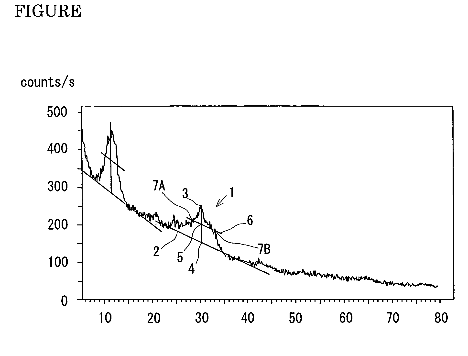
[0025] A secondary battery anode member including a solid electrolyte film having a lithium (Li)-phosphorus (P)-sulfur (S)-oxygen (O) composition was prepared according to the following procedures: First, a rolled copper foil of 10 μm in thickness, 100 mm in length, and 50 mm in width was prepared. The copper foil substrate was fixed on a substrate support in a vacuum evaporation apparatus, and a lithium metal piece used as a raw material was placed in a heating vessel. The pressure was controlled to 1×10⁻⁵ Pa, and a lithium metal film was formed on the copper foil substrate by vacuum evaporation. As a result of measurement by a stylus-type step measuring device, the thickness of the lithium metal film was 5 μm. The rolled copper foil having the lithium metal film was installed at a predetermined position in a solid electrolyte film deposition apparatus. Similarly, a glass substrate was installed in the deposition apparatus to prepare a solid electrolyte film for evaluating performa...
example 2
[0034] A lithium metal film was formed on the same copper foil as that used in Example 1. The copper foil substrate was fixed on a substrate support in a vacuum evaporation apparatus. A lithium metal piece used as a raw material was placed in a heating vessel, and the vapor deposition apparatus was evacuated to form a lithium metal film on the copper foil by vacuum evaporation.
[0035] The oxygen content of the resultant lithium film was analyzed in the depth direction using ESCA5400MC manufactured by PHI Inc. As a result, the oxygen content at the surface was 52 atomic %, but the oxygen content at a depth of 0.46 μm was 5 atomic %. The oxygen at the surface was due to oxidation in the step of handling the sample. The rolled copper foil having the lithium metal film was placed at a predetermined position in the deposition apparatus. Then, the lithium metal was removed by ion bombardment to a depth of about 0.5 μm at which the oxygen content of the lithium metal was 5 atomic %. Then, ...
example 3
[0038] A secondary battery anode member was prepared by the same method as in Example 1 except the heating temperature of an anode material after deposition of a solid electrolyte film and the composition of the solid electrolyte film. First, a rolled copper foil of 10 μm in thickness, 100 mm in length, and 50 mm in width was prepared as a substrate, and a lithium metal film was formed on the copper foil by a vacuum evaporation apparatus. As a result of measurement by a stylus-type step measuring device, the thickness of the lithium metal film was 5 μm. Furthermore, a solid electrolyte film having a lithium (Li)-phosphorus (P)-sulfur (S)-oxygen (O) composition was deposited to a thickness of 0.5 μm on the lithium metal film by a laser ablation method using a target having a composition different from that in Example 1.
[0039] After the deposition, heating was performed in the deposition apparatus at a temperature of 75° C. for 50 hours. As a result, the solid electrolyte film was co...
PUM
| Property | Measurement | Unit |
|---|---|---|
| Temperature | aaaaa | aaaaa |
| Temperature | aaaaa | aaaaa |
| Angle | aaaaa | aaaaa |
Abstract
Description
Claims
Application Information
 - R&D
- Intellectual Property
- Life Sciences
- Materials
- Tech Scout
- Unparalleled Data Quality
- Higher Quality Content
- 60% Fewer Hallucinations
Browse by: Latest US Patents, China's latest patents, Technical Efficacy Thesaurus, Application Domain, Technology Topic, Popular Technical Reports.
© 2025 PatSnap. All rights reserved.Legal|Privacy policy|Modern Slavery Act Transparency Statement|Sitemap|About US| Contact US: help@patsnap.com

