
Acid-lead battery electrode comprising a network of pores passing therethrough, and production method

Inactive Publication Date: 2012-01-05
COMMISSARIAT A LENERGIE ATOMIQUE ET AUX ENERGIES ALTERNATIVES
View PDF0 Cites 11 Cited by
  • Summary
  • Abstract
  • Description
  • Claims
  • Application Information

AI Technical Summary

Benefits of technology

[0011]The object of the invention is to provide an electrode for a lead-acid battery comprising at least one carbon-based porous structure with parallel main faces and lateral faces surrounded by an outer frame, the porous structure, covered by a layer of lead or lead-based alloy, being filled with a lead-based paste, and which remedies the shortcomings of the prior art. More particularly, the object of the invention is to provide an electrode that is compact, light, solid and easy to produce, enabling production of batteries with a high energy density.
[0013]It is a further object of the invention to provide a production method of such an electrode that is easy to implement.

Problems solved by technology

The main problem of lead-acid batteries is their low energy density.
Firstly, the battery current collectors, which also act as mechanical support for the active materials (porous lead-based paste and porous lead oxide-based paste) are in general made from lead (metal), which considerably increases the weight of such a battery.
Secondly, the utilisation factor of an active material, which represents the part of the active material which reacts electrochemically, is low.
Two phenomena in general limit the efficiency of the active materials:during discharging of the battery, a part of the active material undergoes a sulphation phenomenon, which significantly increases the ohmic resistance of the active material and decreases the use of non-sulphated material.
Comparison of these two phenomena limiting the use of the active material therefore indicates that the geometry of the current collectors, in general in the form of a grid, is the major factor limiting the performances of the battery.
In spite of this advantage, the use of these foams remains limited on account of the following problems:the large porosity of these foams (95% vacuum) greatly increases the electric resistance.
Solutions which add a lead frame and connector around the foam to collect the current increase the weight of the electrode and thereby decrease the energy density of the battery.
These methods are moreover costly because they require specific equipment,the irregular structure of the foam makes the step of spreading the active material paste difficult.
A paste arranged in non-homogeneous manner in the pores of the foam reduces the use of the active material and the life expectancy of the battery.
The mechanical stresses generated cause progressive degradation of the battery, in particular of the active material of the positive electrode.
However, this technology is not applicable to current collectors made from carbon foams, such as RVC or carbon / graphite, as compression would cause breaking of the material.
In the absence of separators of AGM type, carbon foams do however have a short lifetime.

Method used


Image

  • Acid-lead battery electrode comprising a network of pores passing therethrough, and production method
  • Acid-lead battery electrode comprising a network of pores passing therethrough, and production method
  • Acid-lead battery electrode comprising a network of pores passing therethrough, and production method

Examples


Embodiment Construction

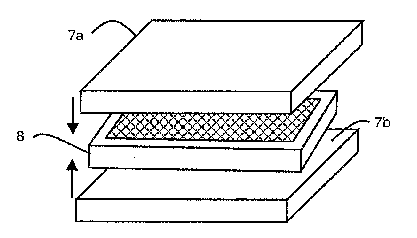
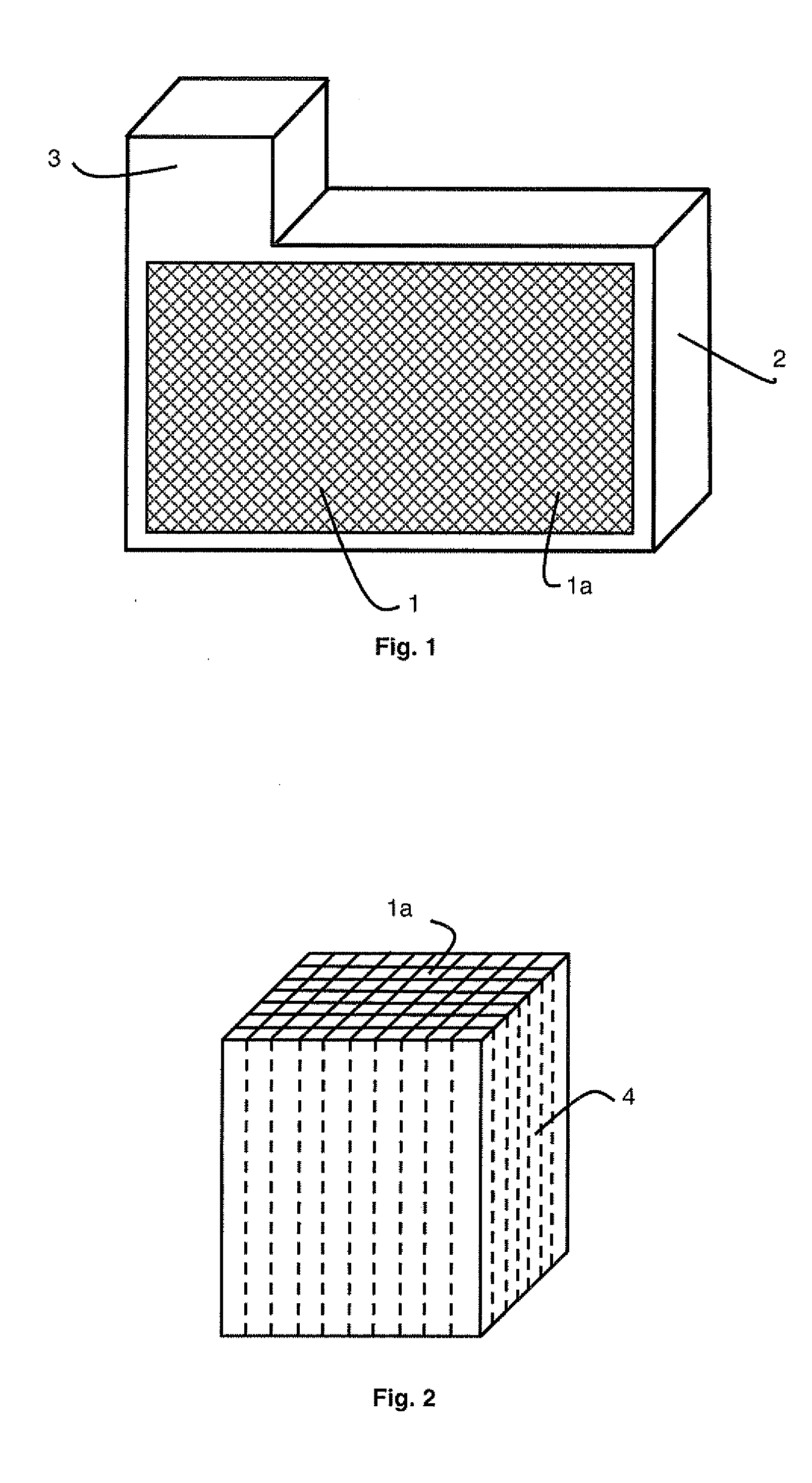
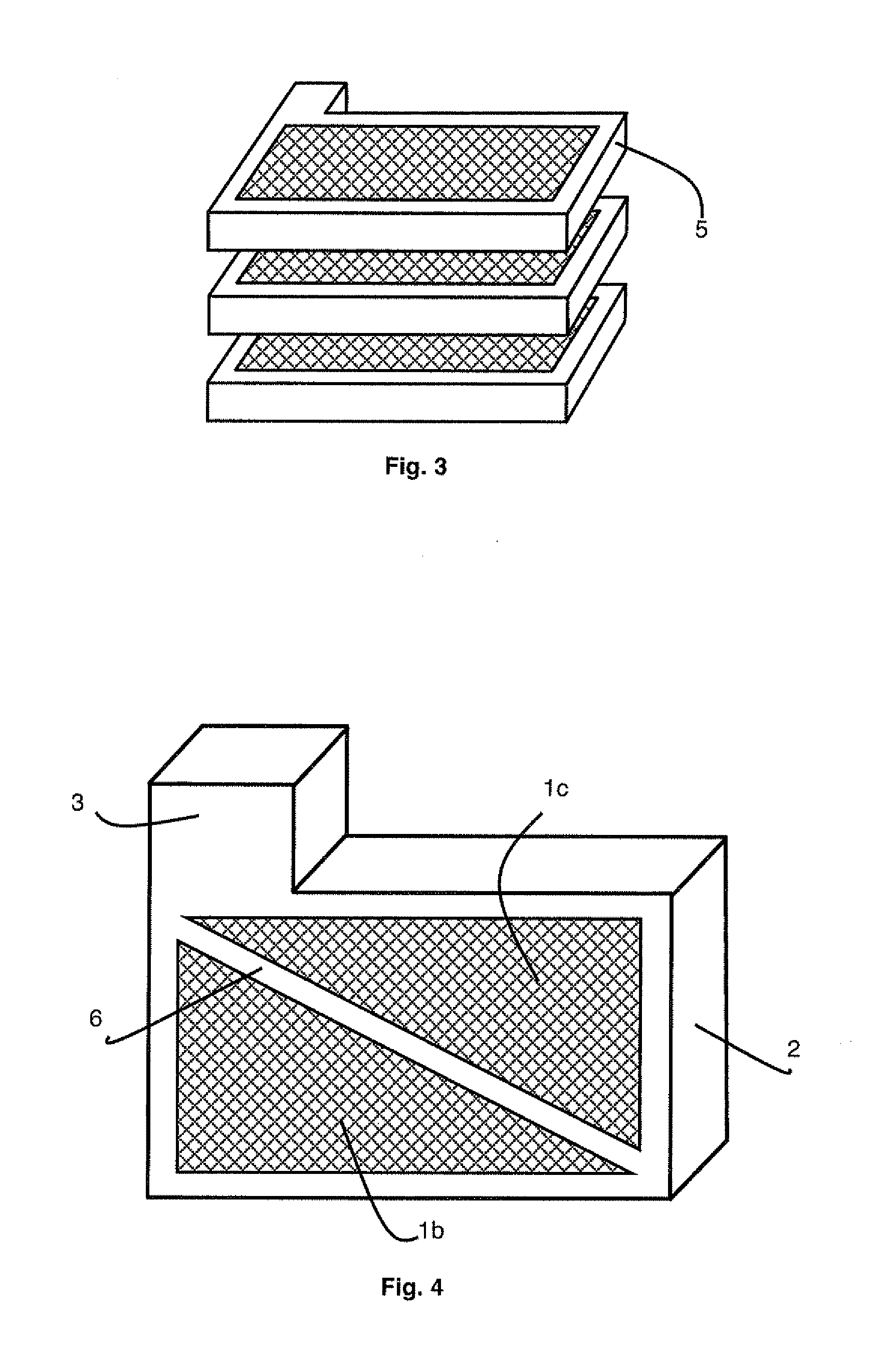
[0026]FIG. 1 represents a particular embodiment of an electrode for a lead-acid battery according to the invention. The electrode comprises a structure 1 provided with a network of pores 1a passing through the structure, from one main face to the other. Pores 1a are perpendicular to the main faces of the grid. They are preferably all identical and separated by thin walls of low porosity (porosity: 5-10%). The cross-section of each pore 1a can be of any type: circular, hexagonal, square, rectangular, etc. Furthermore, a lead-based paste designed to form the active material associated with said electrode fills pores 1a of structure 1. The network formed in this way is preferably a regular network, for example in the form of a honeycomb.

[0027]The lateral faces of structure 1 are further covered by an outer frame 2, which is advantageously bulky, i.e. compact and as little porous as possible.

[0028]Outer frame 2 surrounding structure 1 comprises, in particular in FIG. 1, a connection par...


PUM

PropertyMeasurementUnit
Fractionaaaaaaaaaa
Sizeaaaaaaaaaa
Structureaaaaaaaaaa

Abstract

A structure including a network of parallel, homogeneous pores extending through the structure, and an outer frame around the lateral faces of the structure. The structure and the frame are made of carbon. The electrode is covered by a layer based on lead. The pores are filled with an active material based on lead.

Description

BACKGROUND OF THE INVENTION[0001]The invention relates to a lead-acid battery electrode comprising at least one carbon-based porous structure with parallel main faces and lateral faces surrounded by an outer frame, the porous structure, covered by a lead or lead-based alloy layer, being filled with a lead-based paste.[0002]The invention also relates to a method for production of such an electrode.STATE OF THE ART[0003]Lead-acid batteries are generally formed by a stack of electrochemical cells. Each cell comprises two electrodes each comprising a porous current collector, also called grid, and a lead-based or lead dioxide-based active material, as well as a sulphuric acid-based electrolyte.[0004]The main problem of lead-acid batteries is their low energy density. In the case of Valve-Regulated Lead-Acid Batteries (VRLAB), the energy density is 30 to 40 Wh / kg, whereas the theoretical value of this type of battery is 167 Wh / kg. Two reasons explain the difference between the theoretica...

Claims


Application Information

Patent Timeline
IPC IPC(8): H01M4/38C25D1/00H01M50/437
CPCH01M2/1613H01M2/1673C04B2235/616C04B2111/00853H01M4/0404H01M4/0438H01M4/14H01M4/20H01M4/22H01M4/38H01M4/56H01M4/661H01M4/663H01M4/667H01M4/68H01M4/685H01M4/73H01M4/808H01M4/82H01M10/12Y02E60/126C04B35/524C04B35/83C04B38/0022C04B35/52C04B38/008Y02E60/10H01M50/44H01M50/46Y02P70/50H01M50/437
Inventor KIRCHEV, ANGEL ZHIVKOVKIRCHEVA, NINA
Owner COMMISSARIAT A LENERGIE ATOMIQUE ET AUX ENERGIES ALTERNATIVES
Learn More