Free-running high-speed rail rolling stock traction motor rotor dismantling machine

A technology of vehicle traction and motor rotor, applied in electromechanical devices, manufacturing motor generators, electrical components, etc., can solve the problems of limited range of activities, bruises, low efficiency, etc., to reduce work intensity, increase extraction speed, and walk freely Effect

Inactive Publication Date: 2018-10-30
TANGSHAN COLLEGE
View PDF5 Cites 3 Cited by
  • Summary
  • Abstract
  • Description
  • Claims
  • Application Information

AI Technical Summary

Problems solved by technology

[0002] When maintaining the traction motor of high-speed rail locomotives, the rotor needs to be extracted. The traditional extraction method is to erect the traction motor, lift the rotor out with a crane, and then send the stator and rotor to the maintenance station for maintenance. The range of movement of the vehicle is limited, it is not suitable for the flexible transfer of the traction motor rotor, the efficiency is low, and the workers are easily injured and bruised

Method used


Image

  • Free-running high-speed rail rolling stock traction motor rotor dismantling machine
  • Free-running high-speed rail rolling stock traction motor rotor dismantling machine
  • Free-running high-speed rail rolling stock traction motor rotor dismantling machine

Examples


Embodiment Construction

[0026] The free-running high-speed rail locomotive vehicle traction motor rotor dismantling machine of the present invention will be described in detail below in conjunction with the embodiments and accompanying drawings.

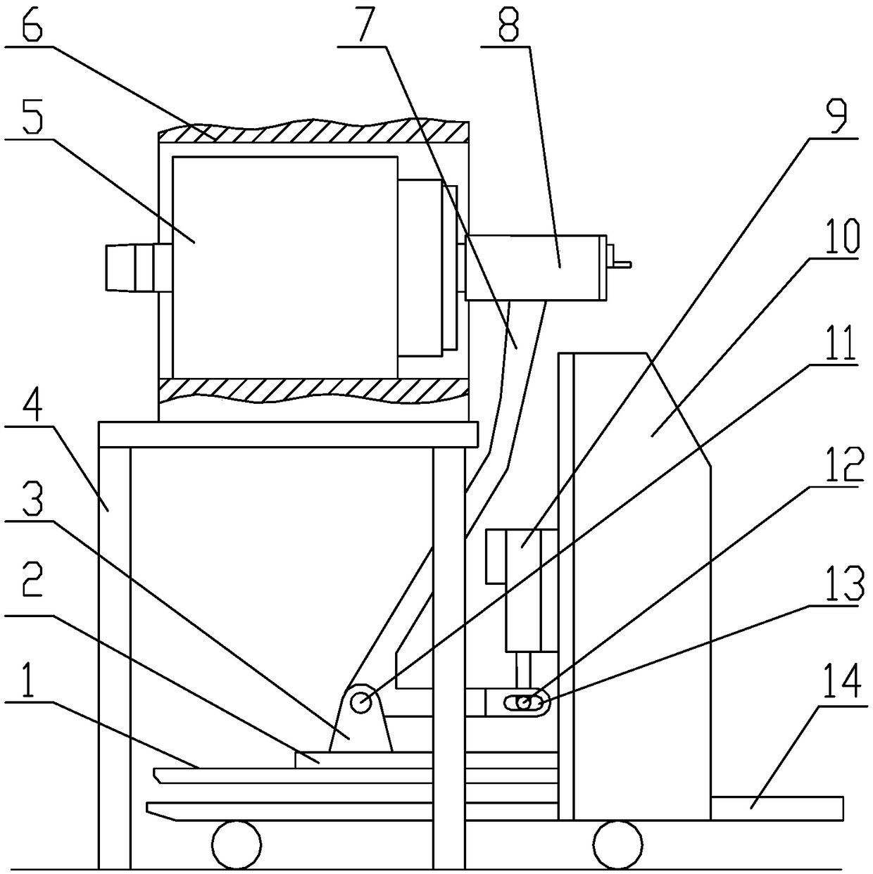
[0027] Such as figure 1 As shown, the traction motor stator 6 is arranged on the motor bracket 4 , and the traction motor rotor 5 is located in the traction motor stator 6 . The free-running high-speed rail locomotive vehicle traction motor rotor dismantling machine of the present invention comprises a storage battery vehicle composed of a storage battery vehicle main body 10, a storage battery vehicle lifting plate 1 arranged on the front side of the storage battery vehicle main body 10, and a storage battery vehicle pedal 14 arranged on the battery storage vehicle main body 10 rear side, The lifting plate 1 of the battery car is fixedly provided with a support base 3 through the base plate 2, and an adjustment rod 7 is hinged on the support base 3, and th...


PUM


Abstract

A free-running high-speed rail vehicle traction motor rotor dismantling machine, comprising a battery car body, a battery car lifting plate arranged on the front side of the battery car body, and a battery car pedal arranged on the rear side of the battery car body. The battery car lifting plate passes through the base plate A support seat is fixedly installed, and an adjustment rod is hinged on the support seat. The upper end of the adjustment rod is fixedly connected with a locking device for locking the traction motor rotor. One end of the bottom of the horizontal structure of the adjustment rod is hingedly connected with the support seat, and the other end forms a horizontal Slot hole, the main body of the battery car is provided with an electric push rod corresponding to the adjustment rod, and the end of the push rod of the electric push rod is integrally formed with a horizontal slot that can be inserted into the adjustment rod to push the adjustment rod to be connected to the hinge point on the support seat. Axis swivel pushrod pin. The invention can improve the extraction speed of the traction motor rotor of the high-speed rail locomotive, reduces the working intensity, and can walk freely, and is suitable for safe and flexible transfer of the traction motor rotor of the high-speed rail locomotive.

Description

technical field [0001] The invention relates to a motor rotor dismantling machine. In particular, it relates to a free-running high-speed rail rolling stock traction motor rotor dismantling machine. Background technique [0002] When maintaining the traction motor of high-speed rail locomotives, the rotor needs to be extracted. The traditional extraction method is to erect the traction motor, lift the rotor out with a crane, and then send the stator and rotor to the maintenance station for maintenance. The range of movement of the vehicle is limited, and it is not suitable for the flexible transfer of the traction motor rotor. The efficiency is low, and the workers are also easy to be injured and bruised. Contents of the invention [0003] The technical problem to be solved by the present invention is to provide a free-running high-speed rail locomotive traction motor rotor dismantling machine that improves the extraction speed of the high-speed rail locomotive traction m...

Claims


Application Information

Patent Timeline
Patent Type & Authority Patents(China)
IPC IPC(8): H02K15/00
CPCH02K15/0006
Inventor 张士强张铜钢齐雪玉汤生安孟凡环杨国权刘乾冀家腾葛存元李德生邓统博毕建新吴猛
Owner TANGSHAN COLLEGE
Why Eureka
Try Eureka