Control device for internal combustion engine

A technology for internal combustion engines and control equipment, which is applied in the direction of engine control, internal combustion piston engines, combustion engines, etc., and can solve problems such as differences in correction levels

Inactive Publication Date: 2017-02-15
TOYOTA JIDOSHA KK
View PDF10 Cites 1 Cited by
  • Summary
  • Abstract
  • Description
  • Claims
  • Application Information

AI Technical Summary

Problems solved by technology

Therefore, there occurs a problem that correction is not performed in the operation region used at the time of transient operation and a difference in correction level occurs between the operation region used at the time of transient operation and the operation region with high frequency of use

Method used


Image

  • Control device for internal combustion engine
  • Control device for internal combustion engine
  • Control device for internal combustion engine

Examples


Embodiment Construction

[0051] Embodiments of the present invention will be described below based on the drawings. Note that elements common to the drawings will be assigned the same reference numerals and redundant descriptions will be omitted. In addition, the present invention is not limited to the following embodiments.

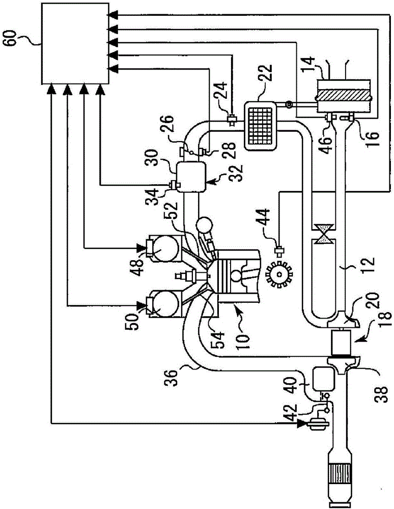
[0052] figure 1 is a schematic diagram showing the configuration of the internal combustion engine controlled by the control device of the present embodiment. Such as figure 1 As shown, the internal combustion engine 10 is configured as a spark ignition engine mounted on a vehicle. However, the internal combustion engine 10 may be a compression ignition engine, and is not particularly limited to the number of cylinders and the cylinder arrangement of the internal combustion engine 10 .

[0053] An air cleaner 14 is provided at the most upstream portion of an intake pipe 12 (intake passage) of the internal combustion engine 10 . On the downstream side of the air cleaner 14, ...


PUM


Abstract

There is provided an art of performing correction of a coefficient in a model calculation formula of an intake valve model that is applied to an internal combustion engine including a turbocharger, in a wide engine operation region. An amendment value [alpha] of a map value a in a correction value calculating operation region is calculated (step 10), and a straight line expressing a relation of a turbocharging pressure Pcmp and a cylinder air filling rate KL is calculated (step S14). A point (Pcmpn, KLn) on the calculated straight line is specified (step S16), and correction of the map value a is performed (step S18). Thereby, a correction value a' of the map value a in an operation region that differs in the turbocharging pressure Pcmp from the correction value calculating operation region is calculated. Similarly, the correction value a' of the map value a in an operation region that differs in valve opening timing EXVT from the correction value calculating operation region, and the correction value a' of the map value a in an operation region that differs in an engine speed NE from the correction value calculating operation region are calculated (steps S20 and S22).

Description

technical field [0001] The invention relates to a control device for an internal combustion engine, in particular a control device for an internal combustion engine including a turbocharger. Background technique [0002] Conventionally, for example, in Patent Document 1, there has been disclosed a method based on an actual measurement value of an operating parameter measured during operation of an internal combustion engine and using a method expressing the relationship between the intake pipe pressure on the downstream side of the throttle valve and the cylinder intake air flow rate. A method of correcting the coefficients of the model calculation formula by comparing the estimated values ​​of the operating parameters calculated by the model calculation formula of the intake valve model. The intake valve model constitutes a part of the air model for estimating the cylinder charging air amount, and therefore, if the coefficient of the model calculation formula of the intake ...

Claims


Application Information

Patent Timeline
Patent Type & Authority Applications(China)
IPC IPC(8): F02D41/00F02D45/00
CPCF02D41/0002F02D41/0007F02D2200/0402F02D2200/0406F02D2200/101F02M35/10091F02M35/10386Y02T10/12Y02T10/40F02D9/08F02D13/0234F02D41/2422F02D41/26
Inventor 田中聪森口龙太郎
Owner TOYOTA JIDOSHA KK
Why Eureka
Try Eureka