System, Device and Method for Displaying a Harmonized Combined Image

a combined image and system technology, applied in the field of systems, devices and methods for displaying harmonized combined images, can solve the problems of certain processing resources and difficult to discern combined images, and achieve the effects of reducing the difference in pixel statistics, reducing processing resources, and avoiding the application of correction factors in image processing routines

Active Publication Date: 2015-03-12
APPL SOLUTIONS ELECTRONICS & VISION
View PDF1 Cites 5 Cited by
  • Summary
  • Abstract
  • Description
  • Claims
  • Application Information

AI Technical Summary

Benefits of technology

[0011]According to an embodiment of the invention, the correction factor is applied in a hardware device acquiring the image. This avoids the need for applying the correction factor to the image or images and, in particular, to each of the pixels making up the image. Therefore, by applying the correction factor in the hardware device acquiring the image, the next image received from the camera has the correction factor applied to all of the pixels of the image acquired by the hardware device. This method requires fewer processing resources as it avoids the need to apply the correction factor to all or even to a substantial proportion of the pixels of the image. Additionally, the method avoids applying the correction to each pixel of the images before displaying the image or combined image. Consequently, a possible delay in displaying the image whilst the correction factor is applied in the image processing routine is avoided.
[0012]A correction factor which is predicted to produce a reduction in the difference in the pixel statistics of the image from each of the two cameras in the overlap region of less than half the difference is calculated. This enables the difference in the pixel statistics to be gradually reduced providing a combined image which is more discernible to the human eye.
[0013]The correction factor may take into account the parameters of the hardware device acquiring the image which affect the pixel statistics. Therefore, the method provides a correction factor which, when applied by the hardware device acquiring the image, is predicted to produce a reduction in the difference in the pixel statistics of less than half of the difference. Thus, the exact effect of the correction factor on the difference in the pixel statistics measured in the overlap region from the next image received from each of the two cameras is not calculated. This again may assist in reducing the processor resources required.
[0014]The method may be reiterated, even if the difference in the pixel statistics and, therefore, the correction factor is very small and even zero. This allows for the situation in which the environment captured by the two cameras suddenly changes after a stable period. For example, a vehicle could emerge from a shady street into bright sunlight. After the image has been harmonized over a period of time in which a correction factor has been calculated and applied to a number of sequentially received images whilst driving along the shady street, the correction factor will tend to be small or even zero. However, as soon as the vehicle emerges into the sun light, the difference in pixel statistics will be much greater, and the correction factor applied will be greater than that applied to the last frame captured within the shady street.
[0015]The pixels of the image within the overlapping area may be predetermined and known. In some embodiments, the pixel statistics of all of the pixels in the overlap region may be measured. However, in some embodiments, only a proportion of the pixels may be selected. By using only a proportion of the pixels in the overlap region, the processing resources required to carry out the method may be reduced.
[0016]In one embodiment, the mean of the luminance in the overlap region of the image from each of the two cameras is determined. This method is simple to perform.

Problems solved by technology

If the brightness and color of the images from adjacent cameras differ, the resulting combined image may be difficult to discern.
However, since cameras on vehicles are typically video cameras capturing a number of images per second, providing correction gain values for each of the images requires certain processing resources which may not be available in the vehicle.

Method used


Image

  • System, Device and Method for Displaying a Harmonized Combined Image
  • System, Device and Method for Displaying a Harmonized Combined Image
  • System, Device and Method for Displaying a Harmonized Combined Image

Examples


first embodiment

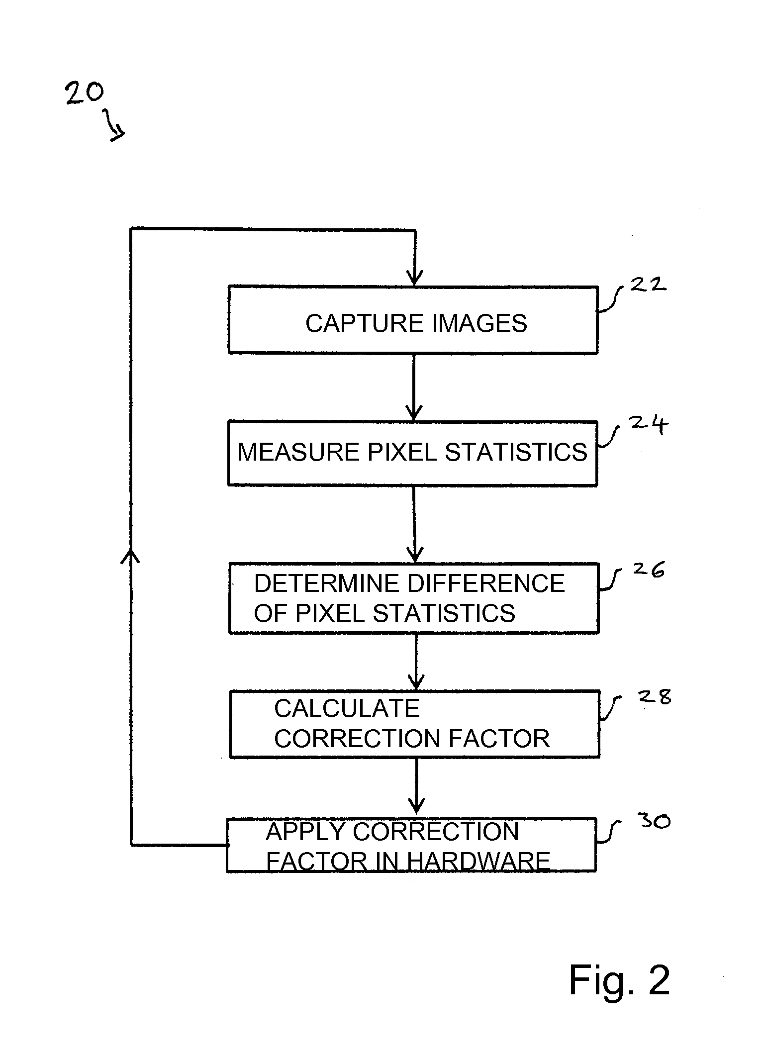
[0037]A flow chart 20 representing a method for harmonizing a combined image is illustrated in FIG. 2. For the purposes of describing the method, two cameras and a single overlap region will be considered first. However, the method may be carried out for all four cameras and all four overlap regions.

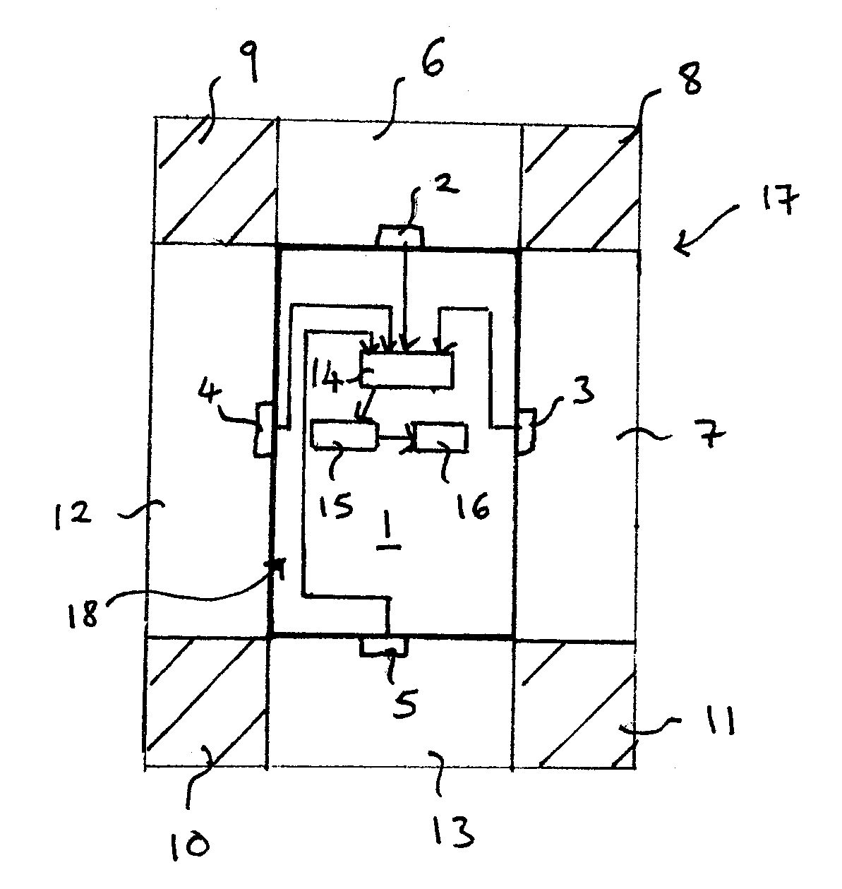
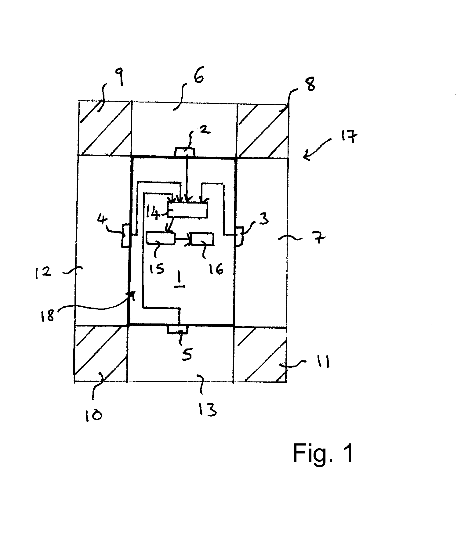
[0038]In step 22, a respective image 6, 7 is received from each of two or more cameras, in particular, from the front camera 2 and the adjacent right camera 3. The same real-world region of the surrounding environment is captured in the overlap region 8 by the front camera 2 in image 6 and by the right camera 3 in image 7. Therefore, the respective pixel statistics of the images 6 and 7 should be the same as one another in the overlap region 8.

[0039]In step 24, the pixel statistics of a predetermined number of predetermined pixels in the overlap region 8 are measured in a given frame of the image 6 from the front camera 2 and of the image 7 of the right camera 3.

[0040]In step 26, the di...

second embodiment

[0061]FIG. 4 illustrates a flow chart 40 representing a method for harmonizing an image according to a In the flow chart 40, the steps 22, 24, 26 and 28 of the flowchart 20 illustrated in FIG. 2 are carried out similarly as described above and are not explained again.

[0062]After the correction factor has been calculated in step 28, in decision diamond 42, it is determined whether the correction factor is predicted to result in a gain value for the hardware device which is higher than a predetermined maximum gain value. In the case that the correction factor is predicted to result in gain value for the hardware device which is higher than a predetermined maximum gain value, the step 44 is performed in which the correction factor is adjusted so that the predicted gain value for the hardware device is less than or equal to the predetermined maximum gain value. This adjusted correction factor is applied in the hardware device in step 30.

[0063]If, in decision diamond 42, the correction ...

third embodiment

[0065]FIG. 5 is a flowchart 50 representing a method for harmonizing an image according to a In the flowchart 50, two steps are performed after an image is received from each of the two or more cameras in step 22. In the first branch, the steps 24, 26, 28, 42, optionally step 44, and step 30 are carried out as in the method illustrated by flowchart 40 in FIG. 4 and are not described again here.

[0066]In the second branch, after step 22, the images from two or more cameras are combined and displayed in step 52. Since the correction factor is applied in the hardware, the images received in step 22 have already had the correction factor from the previous iteration of the method applied to all of the pixels. Therefore, by reiterating the method illustrated by the flowchart 50, the combined image produced in step 52 may be increasingly harmonized in successive frames thereof, and differences in the luminance and, optionally color, in the images received from the different cameras are red...


PUM


Abstract

A method for harmonizing a combined image involves receiving a respective image or image frame from each of two or more cameras, the images from two of the cameras representing the same region in an overlap region, measuring pixel statistics of at least some of the pixels in the overlap region for the image of each of the two cameras, determining a difference in the pixel statistics Δpixel of the image from each of the two cameras in the overlap region, calculating a correction factor Kpixel, wherein the correction factor Kpixel may be predicted to produce a reduction in Δpixel of less than Δpixel/2 when applied to the image of one of the two cameras, applying the correction factor Kpixel in a hardware device acquiring the image, and receiving a further image or image frame from each of the two cameras.

Description

PRIORITY CLAIM[0001]This application is based on and claims the priority under 35 USC 119 of European Patent Application 13183281, filed on Sep. 6, 2013, the entire disclosure of which is incorporated herein by reference.FIELD OF THE INVENTION[0002]The present invention relates to a system, a device and a method for displaying a harmonized combined image, in particular for displaying a harmonized combined image from two or more cameras positioned on a motor vehicle.BACKGROUND INFORMATION[0003]A motor vehicle may include one or more cameras for capturing images of the environment around the vehicle. The images may be used for detecting lanes on the road or traffic signs or may provide the driver with a view of the immediate vicinity of the vehicle. The view of the immediate vicinity of the vehicle may be used to assist the driver when parking the vehicle or may be used to improve safety as the driver is able to view areas which are screened from him in a normal driving position. Haza...

Claims


Application Information

Patent Timeline
Patent Type & Authority Applications(United States)
IPC IPC(8): G06T11/60B60R1/00H04N7/18G06T7/40
CPCG06T11/60H04N7/181B60R1/002G06T7/408G06T3/4038G06T7/90H04N23/698
Inventor RILEY, TOM
Owner APPL SOLUTIONS ELECTRONICS & VISION
Why Eureka
Try Eureka