Packet loss concealment for voice over packet networks

a packet network and packet technology, applied in data switching networks, multiplex communication, instruments, etc., can solve problems such as delay jitter, packets may arrive out of order, packets are delayed or misdirected from the primary data stream, etc., and achieve the effect of fewer processing resources

Active Publication Date: 2006-08-03
TELOGY NETWORKS
View PDF9 Cites 38 Cited by
  • Summary
  • Abstract
  • Description
  • Claims
  • Application Information

AI Technical Summary

Benefits of technology

[0013] The present invention improves over the prior art packet loss concealment (PLC) algorithms, such as the ITU G711 Appendix I PLC algorithm that uses the pitch period to reproduce lost packets, by using the spectral analysis filter to determine a maximum repeatable waveform range to reproduce lost packets. The present invention also uses the filter memory to smooth a signal gap, which removes the 3.75 ms delay that is necessary in the G.711 Appendix I PLC algorithm and thereby uses fewer processing resources. The present invention provides similar or better objective and subjective speech quality as the G.711 Appendix I standard.

Problems solved by technology

Since each packet contains a destination address, they may travel independent of one another and occasionally become delayed or misdirected from the primary data stream.
If delayed, the packets may arrive out of order.
The packets are not only merely delayed relative to the source, but also have delay jitter.
Delay jitter is variability in packet delay, or variation in timing of packets relative to each other due to buffering within nodes in the same routing path, and differing delays and / or numbers of hops in different routing paths.
Packets may even be actually lost and never reach their destination.
Delay jitter is one of the important factors that causes packet loss in a network.
Packet loss can produce interruptions, clicks, pops, hisses and blurring of the sound and / or images as perceived by the user, unless the delay jitter problem can be ameliorated or obviated.
Packets that are not literally lost, but are substantially delayed when received, may have to be discarded at the destination nonetheless because they have lost their usefulness at the receiving end.
Thus, packets that are discarded, as well as those that are literally lost, are all called “lost packets.” Packet loss is a common source of distortion in VOIP.
Packet loss causes the degradation of speech quality as perceived by a user.
From an end-user's point of view, the experience of even a single click or pop during a conversation will greatly reduce the user's satisfaction level with the quality of the entire conversation period.
Customers of telephony services will simply remember the once or twice during a call that degradation was perceived and rate the entire call as poor quality.
Thus, from an end-user's point of view even a single instance of quality degradation has a severely damaging effect on call quality.
The user can rarely tolerate as much as half a second (500 milliseconds) of delay.
Due to packet loss in a packet-switched network employing speech encoders and decoders, a speech decoder may either fail to receive a frame or receive a frame having a significant number of missing bits.
In either case, the speech decoder is presented with the same essential problem—the need to synthesize speech despite the loss of compressed speech information.
Both “frame erasure” and “packet loss” concern a communication channel or network problem that causes the loss of the transmitted bits.
For some applications, however, the aspects of delay, memory consumption, and processing resources (e.g., MIPS) consumption associated with the G.711 Appendix I PLC algorithm are not acceptable.
Even though a single incident of degradation of quality caused by packet loss can subjectively cause significant problems to the perceived call quality by an end user, a significant amount of MIPS are consumed by the prior art PLC algorithm to address a very low packet loss rate.

Method used


Image

  • Packet loss concealment for voice over packet networks
  • Packet loss concealment for voice over packet networks
  • Packet loss concealment for voice over packet networks

Examples


Embodiment Construction

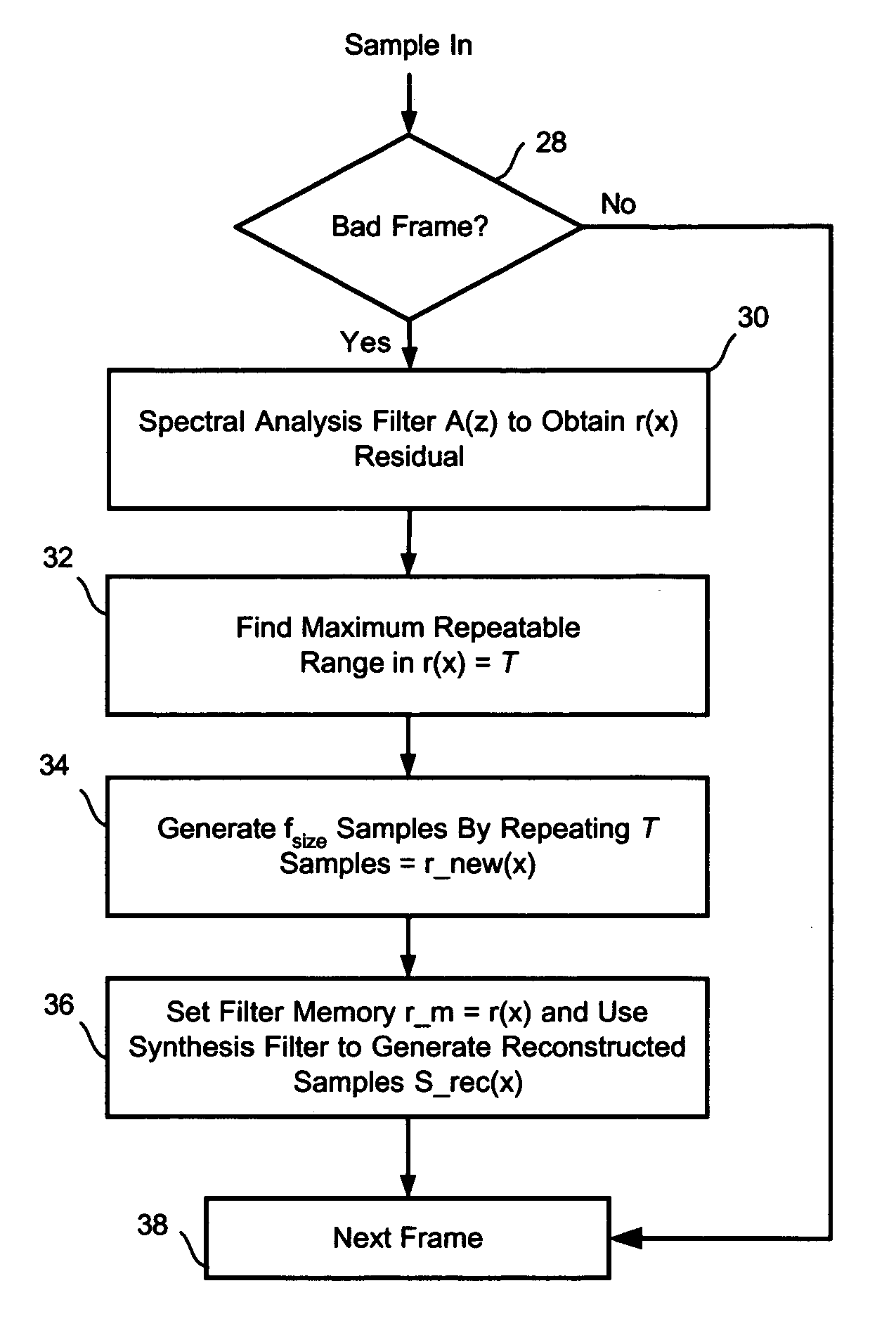
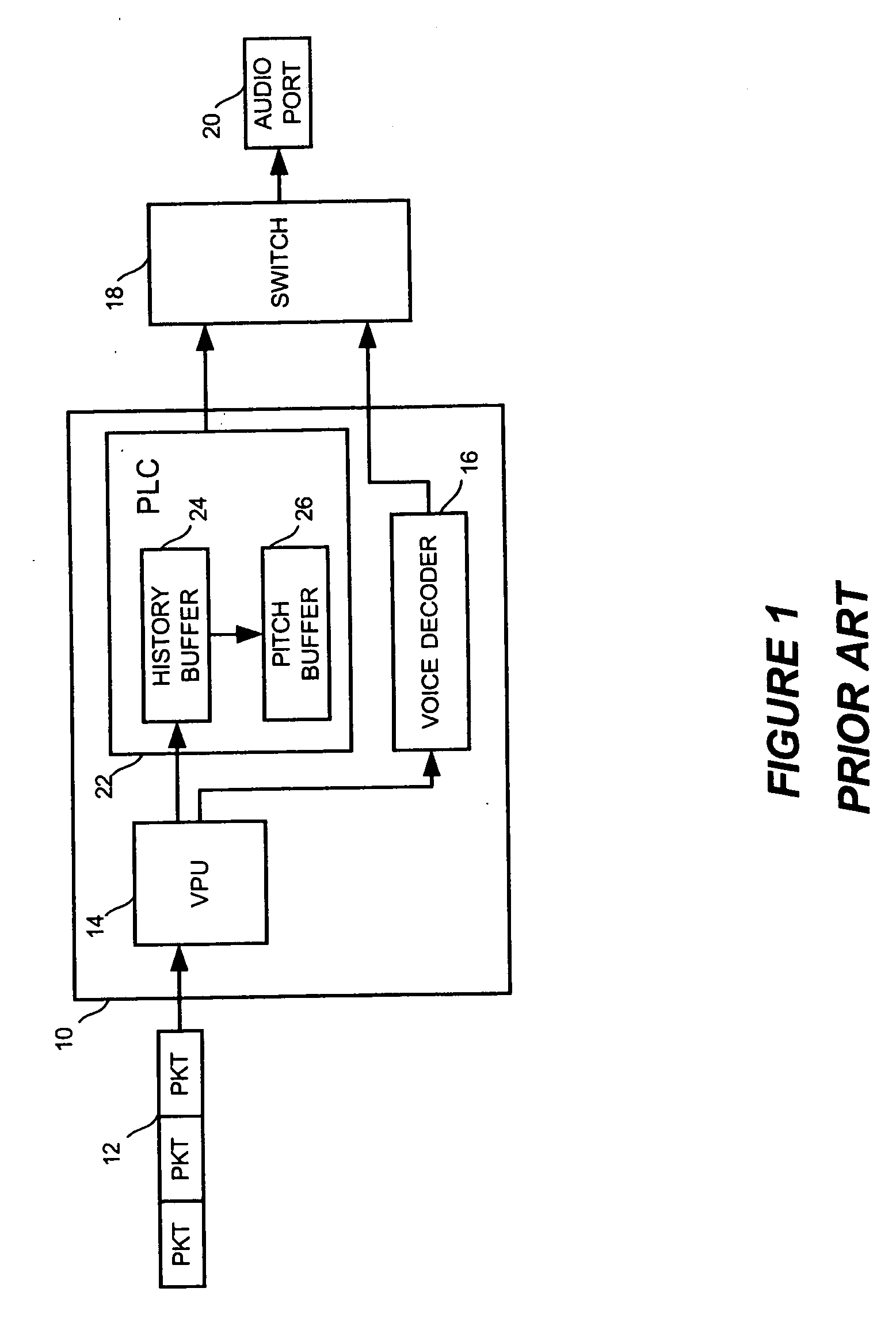
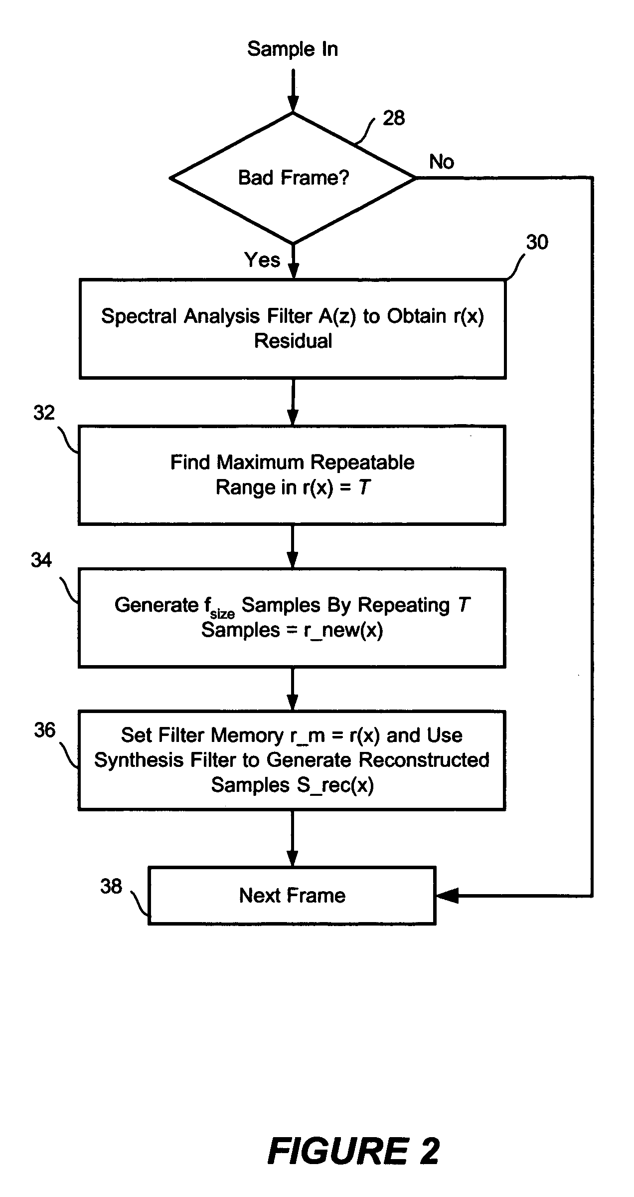
[0020] The present invention includes a method to reduce the memory and processing resources requirements for a packet loss concealment (PLC) algorithm. The method of the preferred embodiment is applied to an ITU G.711 PLC algorithm and is illustrated by the flowchart in FIG. 2. When a receiver 10 determines that a packet from the incoming packet stream is lost 28, the preferred algorithm analyzes 20 ms of samples that have been saved into the history buffer through a spectral analysis filter 30. A spectral analysis filter filters samples for parameters of audible speech that produce the inflections of sound encoded in voice data such as impulse and excitations. FIG. 4 illustrates a block diagram of a spectral analysis filter A(z) 42 that receives input samples 40. The spectral analysis filter A(z) 42 is a linear predictor with prediction coefficients, ai, that is defined as a system whose output is r⁡(n)=∑i=0n⁢ai⁢s⁡(n-i)

where r(n) is the sample index of the residual samples in ti...


PUM


Abstract

A method to reduce memory requirements for a packet loss concealment algorithm in the event of packet loss in a receiver of pulse code modulated voice signals. Packet losses are concealed by using the spectral analysis filter memory to smooth a signal gap and by using a technique for determining a maximum repeatable waveform range instead of using the pitch period to reproduce lost packets. The invention uses fewer processing resources and results in improved performance compared to a packet loss concealment algorithm under G.711 Appendix I standards.

Description

CROSS-REFERENCE TO RELATED APPLICATIONS [0001] None FIELD OF THE INVENTION [0002] The present invention relates generally to providing packet loss concealment in the event of packet loss over a communications network. More specifically, the present invention be used to replace the methods performed by an ITU G.711 Appendix I packet loss concealment algorithm. BACKGROUND OF THE INVENTION [0003] In a packet-switched network, a packet of data often traverses several network nodes as it goes across the network in “hops.” Each packet has a header that contains destination address information for the entire packet. Since each packet contains a destination address, they may travel independent of one another and occasionally become delayed or misdirected from the primary data stream. If delayed, the packets may arrive out of order. The packets are not only merely delayed relative to the source, but also have delay jitter. Delay jitter is variability in packet delay, or variation in timing o...

Claims


Application Information

Patent Timeline
Patent Type & Authority Applications(United States)
IPC IPC(8): H04L12/66
CPCG10L19/005H04L29/06027H04L43/0835H04L65/80H04L65/1101
Inventor LI, DUNLING
Owner TELOGY NETWORKS
Why Eureka
Try Eureka