Quality based video encoding

a video encoder and quality technology, applied in the field of communication systems, can solve the problems of large bandwidth requirements for video content and relatively low utilization level of channels, and achieve the effects of less processing resources, simplified channel loading units, and simplified switching at the channel loader

Inactive Publication Date: 2009-02-26
IMAGINE COMM
View PDF40 Cites 45 Cited by
  • Summary
  • Abstract
  • Description
  • Claims
  • Application Information

AI Technical Summary

Benefits of technology

[0024]An aspect of some embodiments of the invention relates to a preparation unit configured to encode a video stream into blocks and to provide for at least some blocks of the video stream, a plurality of data units representing the block and / or instructions concerning how to generate the plurality of data units. In addition, the preparation unit provides instructions for a plurality of data unit arrangements forming the video stream in respective specific bit rates and / or quality levels. Based on the instructions, channel loading units may load the video stream onto a channel of a specific width and / or at a required quality level. This allows the channel loading units to be simpler and to require less processing resources.
[0025]An aspect of some embodiments of the invention relates to delivering constant bit rate video channels to channel loaders padded with null bytes into a larger constant bit rate stream, such that the padded delivered video channel always has the same size. Transmitting a same size channel at all times makes the switching at the channel loader simpler (in case the number of channels change), as the size of the received channel is constant.

Problems solved by technology

Delivering video content requires large amounts of bandwidth.
While VBR is a good solution for DVD storage of video streams, it may be problematic for transmission on a communication channel, as the utilization level of the channel will be relatively low.

Method used


Image

  • Quality based video encoding
  • Quality based video encoding
  • Quality based video encoding

Examples


Embodiment Construction

Overview

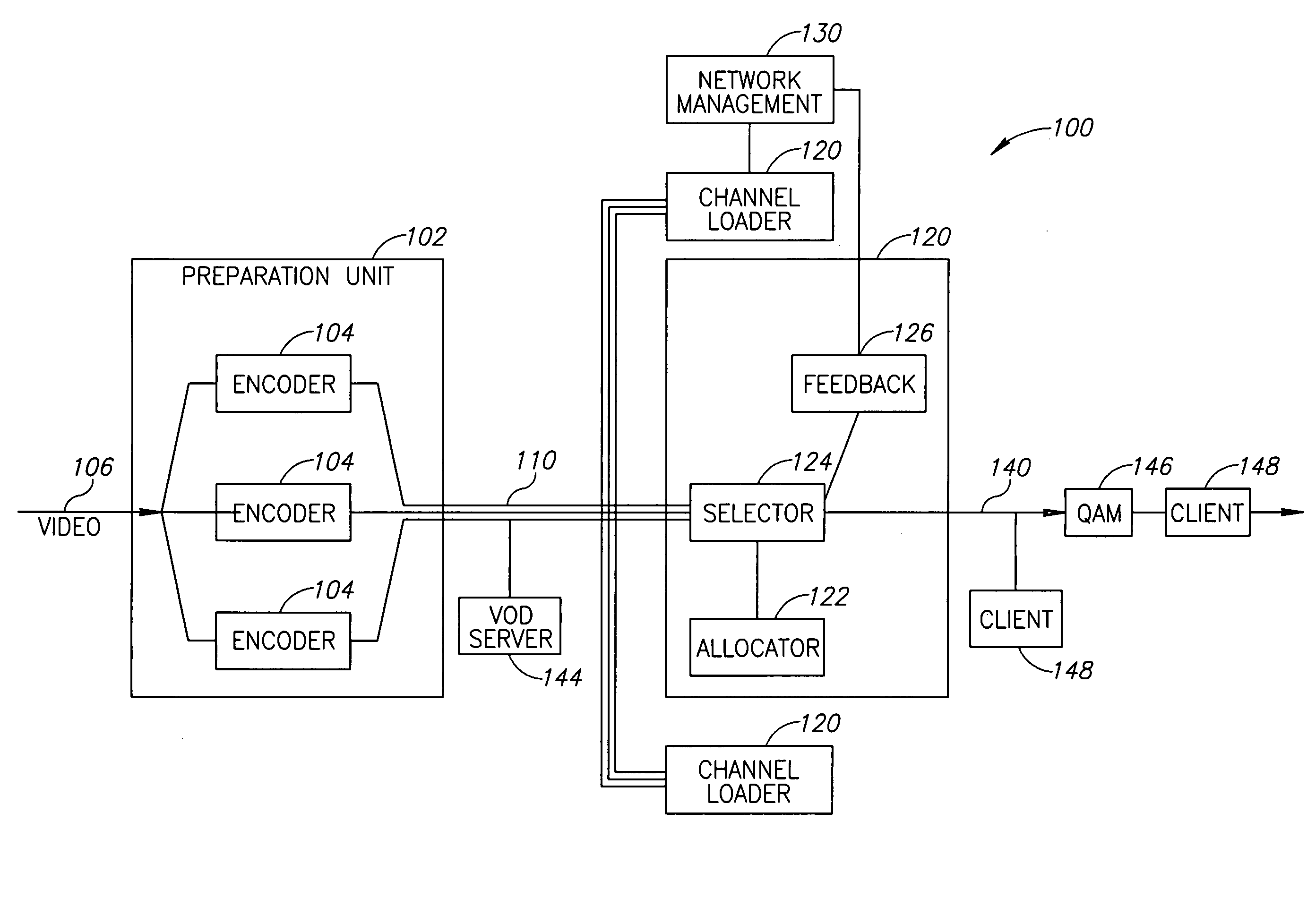
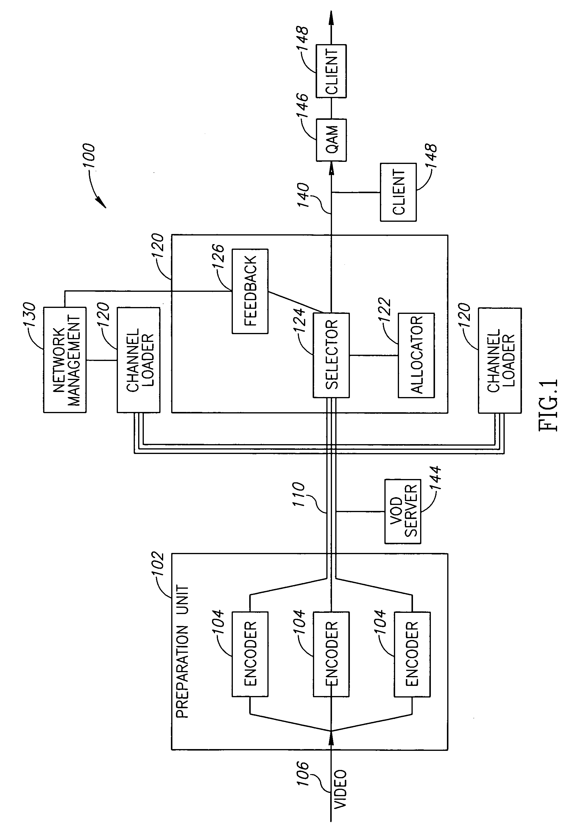
[0077]FIG. 1 is a schematic block diagram of a two-part compression system 100, in accordance with an exemplary embodiment of the invention. Compression system 100 comprises a preparation unit 102 including a plurality of encoders 104 adapted to encode a single video stream received on an input line 106 at a plurality of different quality levels. The encoded streams, along with indications of the respective quality levels of the streams, are provided over a communication channel 110 to one or more channel loaders 120. A selector 124 of channel loader 120 selects, for each time interval of the video stream, a single data unit representation of the video stream for transmission over a communication channel 140, to one or more clients 148 directly or through a quadrature amplitude modulation (QAM) tuner 146, or any other mediation unit. A bandwidth allocator 122 optionally notifies selector 124 about the current bandwidth allocated to the video stream for each time interval, an...


PUM


Abstract

A method of preprocessing a video stream including receiving a video stream formed of a sequence of blocks and setting one or more quality level constraints for the video stream. The method further includes selecting for each of at least a plurality of the blocks of the video stream, one or more sets of compression parameters for compressing the block, such that the block compressed according to the set of parameters meets a respective quality level constraint set for the video stream and generating for each of the sets of compression parameters a corresponding data unit representing the block compressed by the set of compression parameters.

Description

PRIORITY INFORMATION[0001]The present invention claims priority, under 35 USC 119(e), to U.S. Provisional Application No. 60 / 957,639 filed on Aug. 23, 2007.FIELD OF THE INVENTION[0002]The present invention relates to communication systems and in particular to systems for delivery of video signals.BACKGROUND OF THE INVENTION[0003]Delivering video content requires large amounts of bandwidth. Even when optical cables are provided with capacity for many tens of uncompressed channels, it is desirable to deliver even larger numbers of channels using data compression. Therefore, video compression methods, such as MPEG 2, H.264, Windows Media 9 and SMTPE VC-9, are used to compress the video signals. With the advent of video on demand (VoD), the bandwidth needs are even greater.[0004]In the MPEG-2 compression standard, a video stream is compressed into a stream of media units. Each media unit relates to a physical aspect of the compressed video stream, such as a group of pictures (GOP), fram...

Claims


Application Information

Patent Timeline
Patent Type & Authority Applications(United States)
IPC IPC(8): H04N7/26H04N9/64
CPCH04N21/23439H04N21/2365H04N21/23655H04N21/4347H04N19/36H04N19/46H04N19/12H04N19/154H04N19/85H04N21/8456
Inventor GUTMAN, RONSEGEV, DORONESHKOLI, NOAMBOMBELLI, LORENZOBOUOREAU, YVES
Owner IMAGINE COMM
Why Eureka
Try Eureka