
Method and device for estimating a distance

a distance estimation and distance technology, applied in the field of distance estimation methods and devices, can solve the problems of coarse distance estimations based solely on radio signal intensities, blindness of collision warning devices to aircraft not equipped with flarm systems, etc., and achieve the effects of less noise, improved reliability of second distance estimation, and less prone to nois

Inactive Publication Date: 2015-09-03
FLARM TECH
View PDF18 Cites 7 Cited by
  • Summary
  • Abstract
  • Description
  • Claims
  • Application Information

AI Technical Summary

Benefits of technology

The described method is about improving the accuracy of estimating the distance between two objects through the intensity of radio signals. By using a correction factor derived from the first distance estimation, future distance estimations can be made using only the radio signal intensity, without needing additional information about the second position of the radio transmitter. This method can also be applied to different transmitters. The patent describes a collision warning device that uses this method to help prevent hazardous collision conditions in aircraft. The device includes a control unit that carries out the steps of the method.

Problems solved by technology

Although proven highly reliable and very useful to prevent mid-air collisions, such collision-warning devices have the disadvantage to be blind to aircraft which are not equipped with FLARM systems.
However, such distance estimations that are solely based on radio signal intensities are rather coarse as they strongly depend on, e.g., receiver antenna mounting position and other factors.

Method used


Image

  • Method and device for estimating a distance
  • Method and device for estimating a distance
  • Method and device for estimating a distance

Examples


Embodiment Construction

[0064]Description of the Figures:

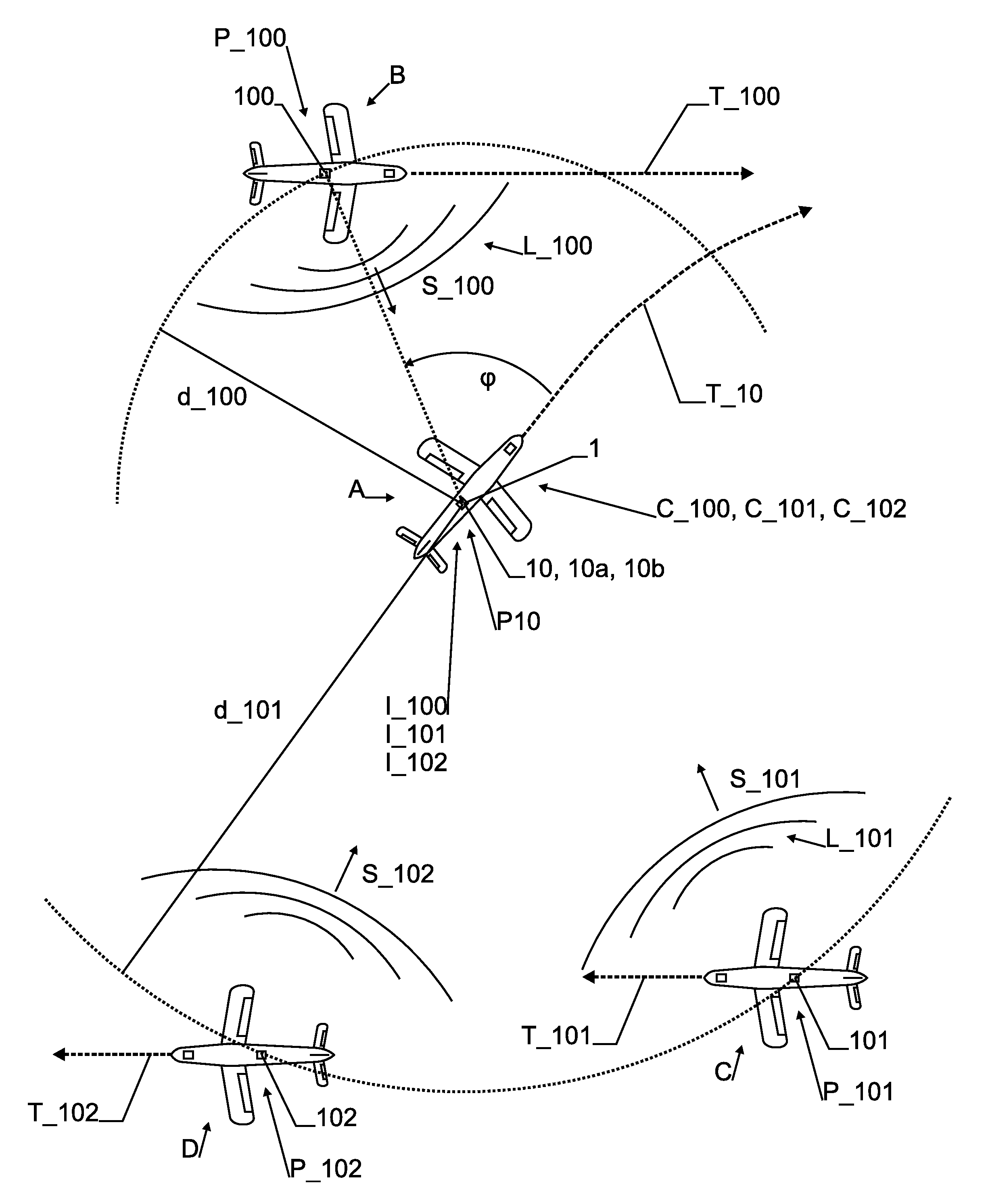
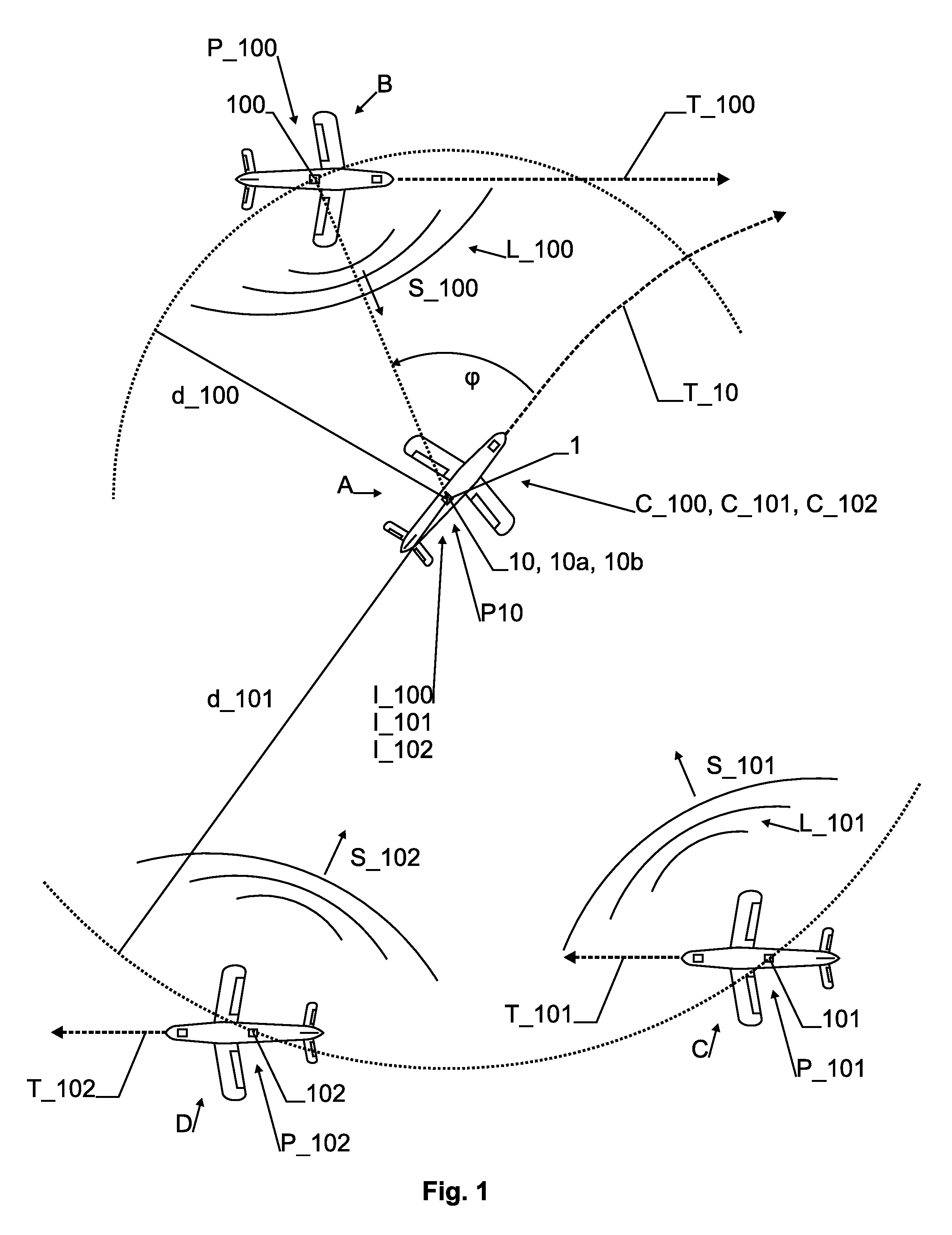
[0065]FIG. 1 shows a top view of an air traffic situation involving 4 aircraft A, B, C, and D. The aircraft A, B, C, and D can be of different types, e.g., comprising gliders, motor planes, commercial aircraft, paragliders, ultralight planes, gyrocopters, helicopters, etc.

[0066]At the shown point in time, aircraft A is at position P_10, aircraft B is at position P_100, aircraft C is at position R101, and aircraft D is at position P_102. Positions can, e.g., be defined by their latitude, longitude, and altitude. The true distances between the aircraft are d_100 between aircraft A and B and d_101 between aircraft A and C and between aircraft A and D (dotted circle segments). Radio signals S_100, S_101, and S_102 are transmitted from onboard transmitters / transponders 100, 101 and 102, respectively, and they comprise second position information L_100 for aircraft B and second position information L_101 for aircraft C, respectively. Second position inform...


PUM


Abstract

An improved method for avoiding mid-air collision in aviation is disclosed. The method relies on a calibration of radio signal intensities I with radio signal encoded position information L. In other words, after a first reception of a radio signal S advantageously comprising remote aircraft position information L, the radio signal intensity I is measured and a correction factor C is derived. During a next encounter of the radio signal S, a second distance estimation d can be derived using the signal intensity I and the correction factor C. Preferably, relative positioning data is acquired together with the correction factor C and a plurality of correction factors for different relative positions is combined in an at least partly continuous correction function.

Description

TECHNICAL FIELD[0001]The present invention relates to a method for deriving a correction factor for improving the precision of a distance estimation. Furthermore, the present invention relates to a method and device for deriving such an improved distance estimation using such a correction factor, in particular for use in aviation and vehicles.INTRODUCTION AND BACKGROUND ART[0002]State-of-the-art traffic-awareness collisionwarning devices for aviation (such as FLARM, see, e.g., http: / / www.flarm.com / as accessed on May 13, 2012) constantly monitor their own three-dimensional (3D) position, e.g., via GNSS (Global Navigation Satellite Systems), inertial navigation systems, or combined data. This 3D position information (called “second position inn formation” herein) is then transmitted encoded in a digital radio signal. FLARM devices in other aircraft receive this radio signal, decode the associated 3D position information, display the other aircraft position, and compare this 3D positio...

Claims


Application Information

Patent Timeline
Patent Type & Authority Applications(United States)
IPC IPC(8): G01S5/02G08G5/04G08G5/00G01S13/933
CPCG01S5/021G01S5/0284G08G5/04G01S5/0278G08G5/0095G01S5/0072G08G5/045G01S13/103G01S13/42G01S13/765G08G5/0082G01S13/933
Inventor ROTHACHER, URSMADER, URBAN
Owner FLARM TECH
Learn More