Stamping mould for motor connector

A technology for stamping dies and connecting parts, which is applied in the field of stamping dies for motor connecting parts, can solve the problems of difficult to guarantee processing accuracy, low product qualification rate, low processing efficiency, etc., and achieves the effect of compact layout, improved qualification rate and plate saving.

Inactive Publication Date: 2017-02-22
WUXI TAICHANG PRECISION MACHINERY CO LTD
View PDF6 Cites 1 Cited by
  • Summary
  • Abstract
  • Description
  • Claims
  • Application Information

AI Technical Summary

Problems solved by technology

[0002] like figure 1 The schematic diagram of the structure of the motor connector to be processed is shown. It can be seen from the figure that the motor connector has an irregular shape, and multiple stamping dies are required for processing, and each die is trimmed separately, so that endless processing The efficiency is low, and the processing accuracy of the product is difficult to guarantee after being processed by multiple molds, resulting in a low product qualification rate, and a large amount of scraps are cut off during the processing of each motor connector, which is a waste of raw materials

Method used


Image

  • Stamping mould for motor connector
  • Stamping mould for motor connector
  • Stamping mould for motor connector

Examples


Embodiment Construction

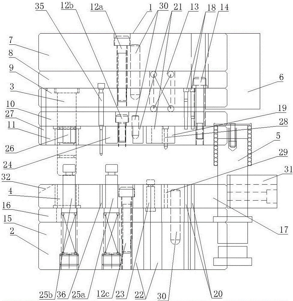
[0015] like figure 2 , image 3 As shown, the upper mold body 1 and the lower mold body 2 are included, and the upper mold body 1 and the lower mold body 2 are respectively guided by the inner guide post 3 and the inner guide sleeve 4, and the outer guide post 5 and the outer guide sleeve 6. The upper mold body 1 includes an upper mold base 7 and an upper backing plate 8, an upper splint 9, a stop plate 10 and a stripping plate 11 installed under the upper die base 7 in sequence, and the upper backing plate 8 and the upper splint 9 pass through The fixing bolt 12a is fixedly connected, and the stop plate 10 and the stripping plate 11 are fixedly connected by the fixing bolt 12b and installed under the upper clamping plate 9 by the spring 13 and the contour sleeve 14. The lower mold body 2 includes the lower mold base 15 and The lower backing plate 16 and the lower template 17 installed on the lower mold base 15 in sequence, the lower template 17 and the lower backing plate 1...


PUM


Abstract

The invention provides a stamping mould for a motor connector, and the stamping mould can be used for continuously processing, is continuous in forming, is high in processing efficiency, is high in processing precision, is high in product qualification rate, and further can save raw materials. The stamping mould comprises an upper mould body and a lower mould body, wherein the upper mould body and the lower mould body are guided and closed in a matched mode through an inner guide post, an inner guide sleeve, an outer guide post and an outer guide sleeve; the upper mould body comprises an upper mould base as well as an upper gasket, an upper clamping plate, a stop plate and a stripper plate which are sequentially mounted under the upper mould base; the upper gasket is fixedly connected with the upper clamping plate through a fixed bolt; the stop plate is fixedly connected with the stripper plate through a fixed bolt; the stop plate and the stripper plate are mounted under the upper clamping plate through a spring and an equal-height sleeve; the lower mould body comprises a lower mould base as well as a lower gasket and a lower molding board which are sequentially mounted on the lower mould base; the lower molding board and the lower gasket are fixedly arranged on the lower mould base; and the upper mould body and the lower mould body are sequentially equipped with a positioning trimming mechanism, a punching mechanism, a first dropping mechanism and a second dropping mechanism in a plate conveying direction.

Description

technical field [0001] The invention relates to hardware processing equipment, in particular to a stamping die for a motor connector. Background technique [0002] like figure 1 The schematic diagram of the structure of the motor connector to be processed is shown. It can be seen from the figure that the motor connector has an irregular shape, and multiple stamping dies are required for processing, and each die is trimmed separately, so that endless processing The efficiency is low, and the processing accuracy of the product is difficult to guarantee after being processed by multiple molds, resulting in a low product qualification rate, and a large amount of scraps are cut off during the processing of each motor connector, which is a waste of raw materials. Contents of the invention [0003] In view of the above problems, the present invention provides a stamping die for motor connectors, which can be continuously processed and formed, has high processing efficiency, high...

Claims


Application Information

Patent Timeline
Patent Type & Authority Applications(China)
IPC IPC(8): B21D37/08
CPCB21D37/08
Inventor 陈建华
Owner WUXI TAICHANG PRECISION MACHINERY CO LTD
Why Eureka
Try Eureka