
Gantry-type bar cutting machine allowing cutting length to be adjustable

A cutting-length, gantry-type technology, applied in metal sawing equipment, sawing machine equipment, metal processing equipment, etc., can solve the problems of low cutting efficiency, time-consuming, and the cutting blade cannot be moved.

Active Publication Date: 2017-02-22
CHONGQING JIEJIATAI MACHINE MFG CO LTD
View PDF7 Cites 3 Cited by
  • Summary
  • Abstract
  • Description
  • Claims
  • Application Information

AI Technical Summary

Problems solved by technology

The current cutting equipment can only cut the next section of bar after each cutting action is completed, and the cutting blade cannot move. When the next section of bar is to be cut, the operator can only pass through after the operator removes the cut bar. Moving the bar to be cut manually or mechanically is time-consuming and the cutting efficiency is low

Method used


Image

  • Gantry-type bar cutting machine allowing cutting length to be adjustable
  • Gantry-type bar cutting machine allowing cutting length to be adjustable
  • Gantry-type bar cutting machine allowing cutting length to be adjustable

Examples


Embodiment Construction

[0017] In order to make the technical means, creative features, goals and effects achieved by the present invention easy to understand, the present invention will be further described below in conjunction with specific embodiments.

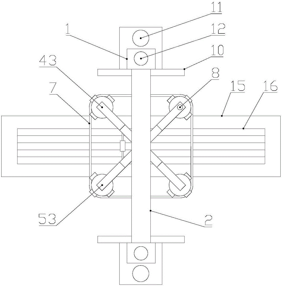
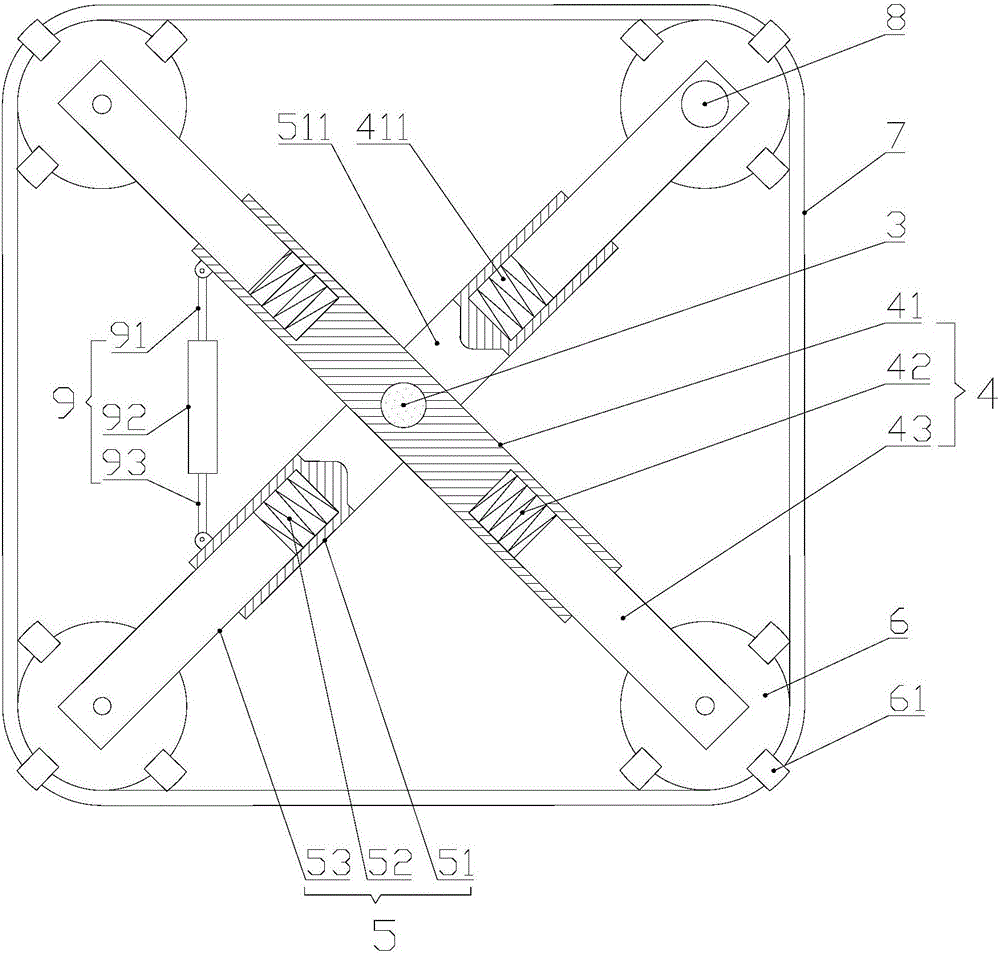
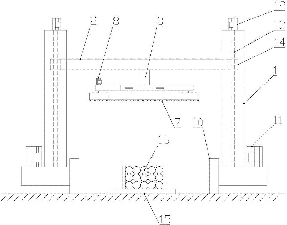
[0018] see Figure 1-5 , the present invention provides a technical solution: a gantry-type bar cutting machine with adjustable cutting length, comprising:

[0019] The gantry frame has two gantry columns 1 and a gantry beam 2 that connects the two gantry columns 1 and can move up and down;

[0020] The cutting mechanism comprises the first and second brackets 4 and 5 of equal length horizontally arranged below the gantry beam 2, four guide wheels 6 respectively arranged at both ends of the first and second brackets 4 and 5, and four guide wheels 6 sleeved on the two ends of the first and second brackets 4 and 5. The band saw blade 7 on the outside, the cutting motor 8 and the adjustment mechanism 9 that drive any guide wheel 6 to rotate, the fir...


PUM


Abstract

The invention discloses a gantry-type bar cutting machine allowing the cutting length to be adjustable. The gantry-type bar cutting machine comprises a gantry framework, a cutting mechanism, a running mechanism, a feeding mechanism and a work table, wherein the gantry framework is provided with two gantry stand columns and a gantry cross beam which is used for connecting the two gantry stand columns and can move up and down; the cutting mechanism comprises a first support, a second support, four guide wheels, band saw strips, a cutting motor and an adjusting mechanism, the first support and the second support are transversely arranged below the gantry cross beam and are equal in length, the four guide wheels are arranged at the two ends of the first support and the two ends of the second support correspondingly, the band saw strips are arranged on the outer sides of the four guide wheels in a sleeving manner, and the cutting motor drives any guide wheel to rotate; the running mechanism is arranged at the lower ends of the gantry stand columns and used for driving the gantry stand columns to move left and right; the feeding mechanism is arranged on the gantry stand columns and used for driving the gantry cross beam to move up and down; and the work table is located between the two gantry stand columns. According to the bar cutting machine of the structure, two sections of bars can be cut out from one single bar through cutting motion each time, moreover, the cutting mechanism is moved to carry out cutting of the next time, and the cutting efficiency is improved greatly compared with that of traditional cutting equipment.

Description

technical field [0001] The invention relates to a gantry type bar cutting machine with adjustable cutting length, which belongs to the technical field of cutting. Background technique [0002] Bars are used when processing slender workpieces such as rods and shafts, and cutting equipment is used when cutting bars. The current cutting equipment can only cut the next section of bar after each cutting action is completed, and the cutting blade cannot move. When the next section of bar is to be cut, the operator can only pass through after the operator removes the cut bar. Moving the bar to be cut manually or mechanically is time-consuming and the cutting efficiency is low. Contents of the invention [0003] In view of this, the object of the present invention is to provide a gantry-type bar cutting machine with adjustable cutting length. Each cutting action can cut two sections of bars from a single bar, and the cutting length is adjustable. By moving The cutting mechanism ...

Claims


Application Information

Patent Timeline
Patent Type & Authority Applications(China)
IPC IPC(8): B23D55/06B23D55/08B23D55/02B23D53/04
CPCB23D53/04B23D55/02B23D55/065B23D55/088
Inventor 夏家鑫马东
Owner CHONGQING JIEJIATAI MACHINE MFG CO LTD
Learn More