Automatic assembly equipment for LED (Light-Emitting Diode) bulb lamp

An LED bulb lamp and automatic assembly technology, applied in metal processing equipment, assembly machines, manufacturing tools, etc., can solve the problems of inability to automate large-scale production, low production efficiency, and low product quality, and achieve large-scale automation The effect of large-scale production, reduction of waste generation rate, and improvement of product quality

Active Publication Date: 2017-02-22
广东立迪智能科技有限公司
8 Cites 28 Cited by

AI-Extracted Technical Summary

Problems solved by technology

[0003] LED bulbs are widely used. At present, manual assembly is used in the production of LED bulbs. This manual assembly process has m...

Method used

After the lamp holder of this embodiment is loaded, the transmission device 7 transmits the lamp holder to the wire arrangement device, and the wires on the lamp holder are straightened upwards by the wire management mechanism 21, and then the two wires are pulled by the wire trimmer 22 The wires are cut to the same height; the transmission device 7 transmits the lamp holder to the lamp holder installation device 3 to install the lamp holder; after the lamp holder is installed, the transmission device 7 then transfers the lamp holder to the wi...

Abstract

The invention relates to the technical field of manufacturing of an LED lamp and particularly relates to automatic assembly equipment for an LED bulb lamp. The automatic assembly equipment comprises a lamp holder feeding device, a wire embedding device, a lamp cap mounting device, a wire bending device, a lamp nail mounting device, a blanking device and a conveying device, wherein the wire embedding device is used for settling wires on a lamp holder; the lamp cap mounting device is used for mounting a lamp cap on the lamp holder; the wire bending device is used for bending the wires; the lamp nail mounting device is used for mounting a lamp nail at the upper end of the lamp cap; the conveying device is used for conveying the lamp holder among all devices; the wire embedding device comprises a wire embedding mechanism and a wire shearing mechanism; the lamp nail mounting device comprises a lamp nail feeding mechanism and a riveting mechanism, wherein the riveting mechanism is used for fixedly connecting the lamp nail with the lamp holder. By the structure, the automatic assembly equipment provided by the invention has the advantages of realizing automatic assembly of the lamp cap and the lamp holder of the LED bulb lamp, improving the production efficiency, improving the product quality, reducing generation rate of waste products and realizing automatic large-scale production.

Application Domain

Technology Topic

Image

  • Automatic assembly equipment for LED (Light-Emitting Diode) bulb lamp
  • Automatic assembly equipment for LED (Light-Emitting Diode) bulb lamp
  • Automatic assembly equipment for LED (Light-Emitting Diode) bulb lamp

Examples

  • Experimental program(1)

Example Embodiment

[0029] Attached below figure 1 Attached Figure 13 , And specific implementations to further illustrate the present invention.
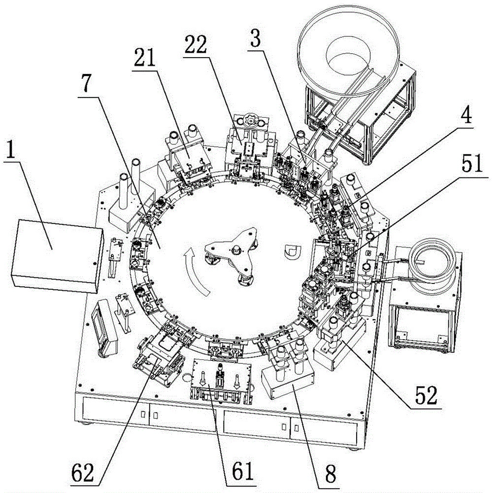
[0030] Such as figure 1 As shown, an automatic assembly equipment for an LED bulb lamp includes a lamp holder feeding device 1, a wire management device for arranging the wires on the lamp holder, a lamp holder mounting device 3 for installing the lamp holder on the lamp holder, and the wire folding The bent wire bending device 4, the lamp nail installation device for installing the lamp nail on the upper end of the lamp cap, the blanking device and the conveying device 7 for transferring the lamp holder between the various devices, the wire management device includes a wire management mechanism 21 and The wire trimming mechanism 22, the lamp nail installation device includes a lamp nail feeding mechanism 51 and a riveting mechanism 52 for fixedly connecting the lamp nail and the lamp socket.
[0031] After the lamp holder is loaded in this embodiment, the conveying device 7 conveys the lamp holder to the wire management device, and the wire on the lamp holder is straightened up by the wire management mechanism 21, and then the two wires are cut into The same height; the conveying device 7 conveys the lamp holder to the lamp holder installation device 3 to install the lamp holder; after the lamp holder is installed, the conveying device 7 then conveys the lamp holder to the wire bending device 4 to bend the wires to prevent subsequent lamp installation When nailing, the wire interferes with the lamp nail and affects the normal installation of the lamp nail; after the wire is bent, the lamp nail is installed and the lamp nail and the lamp cap are riveted and fixed together; the LED bulb lamp is assembled to realize the lamp cap and the lamp holder. Automated assembly, to provide production efficiency, improve product quality, reduce the rate of waste generation, and realize automated mass production.
[0032] Such as figure 2 As shown, in this embodiment, the wire management mechanism 21 includes a support A211, the support A211 is provided with a manipulator A212 for fixing the lamp holder, and the manipulator A212 is provided with a manipulator B213 for straightening wires. And the driving mechanism A214 for driving the manipulator B213 to move up and down. After the manipulator A212 clamps and fixes the lamp holder, the driving mechanism A214 drives the manipulator B213 to move down and clamps the exposed outside of the lamp holder. The driving mechanism A214 drives the manipulator B213 to move up and move The wire is straightened, and the driving mechanism A214 in this embodiment is an air cylinder.
[0033] Such as Figure 3 to Figure 4 As shown, in this embodiment, the thread trimming mechanism 22 includes a support B221 provided with a base 222 and a driving mechanism B223 for driving the base 222 to move up and down, and the base 222 is provided with a first scissors Mechanism and a second scissors mechanism arranged opposite to the first scissors mechanism. The first scissors mechanism includes a push block A224 and a driving mechanism C225 for driving the push block A224 to move linearly. A scissors blade A226 is provided at the lower end of the push block A224. The second scissor mechanism includes a push block B227 and a drive mechanism D228 for driving the push block B227 to move linearly. The lower end of the push block B227 is provided with a scissor blade B229, the drive mechanism B223 drives the substrate 222 to move down, and the drive mechanism C225 drives The scissor blade A226 moves, and the drive mechanism D228 drives the scissor blade B229 to move, so that the scissor blade A226 and the scissor blade B229 cut the wires so that the two telecommunication cables have the same height. The drive mechanism B223 in this embodiment is a screw drive mechanism; the drive mechanism C225 and the drive The D228 mechanism is an air cylinder.
[0034] Such as Figure 5 to Figure 6 As shown, in this embodiment, the lamp holder mounting device 3 includes a lamp holder feeding passage 31, and a lamp holder feeding vibration plate 32 is provided at the feeding port of the lamp holder feeding passage 31, and the outlet of the lamp holder feeding passage 31 A lamp holder installation mechanism is provided at the material opening, the lamp holder installation mechanism includes a manipulator C32 for fixing the lamp holder, and a positioning block mechanism for positioning the lamp holder and a push rod mechanism for connecting the lamp holder and the lamp holder are arranged above the manipulator C32, The positioning block mechanism includes a positioning block 33 and a driving mechanism E34 for driving the positioning block 33 to move up and down. The push rod mechanism includes a push rod 35 and a driving mechanism F36 for driving the push rod 35 to move up and down. , The manipulator C32 clamps the lamp holder, the lamp holder is loaded onto the positioning block 33, and the positioning block 33 clamps the lamp holder to ensure that the lamp holder is directly above the lamp holder. The driving mechanism F36 drives the push rod 35 to move down to push the lamp holder and the lamp holder to be assembled Together, the driving mechanism E34 and the driving mechanism F36 in this embodiment are both air cylinders.
[0035] Such as Figure 7 to Figure 8 As shown, in this embodiment, the wire bending device 4 includes a support C41, and the support C41 is provided with a positioning base 42 and a driving mechanism G47 for driving the positioning base 42 to move up and down. The lower end of the base 42 is provided with a slot for the upper end of the lamp holder to pass through, a first bending mechanism 43 is provided on the side of the slot, and the upper end of the positioning base 42 is provided with a hollow tube 44 and a second bending Bending mechanism 45, the upper end of the hollow tube 44 is connected with the positioning base 42, and the lower end of the hollow tube 44 is provided with a die 46 for covering the lamp cap; the first bending mechanism 43 includes a push Block C431 and a driving mechanism H432 for driving the push block C431 to move linearly; the second bending mechanism 45 includes a cone 451 and a driving mechanism I452 for driving the cone 451 to move up and down, the cone 451 is set in the center Inside the empty tube 44, first the first bending mechanism 43 starts to work, and the driving mechanism H432 drives the push block C431 to push toward the wire, so that the upper half of the wire is bent at 90 degrees. At this time, the wire includes a vertical portion and a bending portion; The driving mechanism H432 then drives the push block C431 to reset; the second bending mechanism 45 starts to work, and the driving mechanism I452 drives the cone 451 to move down to press the bent part of the wire into a U-shape. The purpose is to install the lamp nail in the later process. The nail head of the lamp nail passes through the U-shaped opening of the wire bending part to prevent the wire from interfering with the lamp nail and affecting the normal installation of the lamp nail. In this embodiment, the driving mechanism G47, the driving mechanism H432, and the driving mechanism I452 are all cylinders.
[0036] Such as Figure 9 to Figure 10 As shown, the lamp nail feeding mechanism 51 includes a lamp nail feeding channel 511, the lamp nail feeding channel 511 is provided with a lamp nail feeding vibrating plate 512 at the feeding port, and the lamp pin feeding channel 511 has a discharge port. A stopper mechanism and a lamp nail installation mechanism are provided at the location; the stopper mechanism includes a pressing rod A513 and a driving mechanism J514 for driving the pressing rod A513 to move up and down; the lamp nail installation mechanism includes a pressing rod B515 and a driving mechanism The driving mechanism K516 that moves the rod B515 up and down, the lamp nails start to feed, the driving mechanism J514 drives the pressing rod A513 to press down, blocking the lamp nails behind the outlet of the lamp feeding channel 511 from continuing to feed, and the driving mechanism K516 drives the pressing rod B515 down Press the lamp pin in front of the discharge port of the lamp pin feeding channel 511 into the slot on the top of the lamp cap; in this embodiment, the driving mechanism J514 and the driving mechanism K516 are both air cylinders.
[0037] Such as Figure 11 to Figure 12 As shown, in this embodiment, the riveting mechanism 52 includes a fixed mold base 521 for pressing the lamp cap and a driving mechanism L522 for driving the fixed mold base 521 to move up and down. The fixed mold base 521 is provided with a pressing rod C523. The upper end of the pressure rod C523 is provided with a driving mechanism M524 for driving the pressure rod C523 to move up and down, the lower end of the pressure rod C523 is provided with a riveting head 525 for riveting the lamp nail and the lamp cap, and the driving mechanism L522 drives the fixed mold The seat 521 moves down to press the lamp cap, the driving mechanism M524 drives the pressing rod C523 to press down, and the riveting head 525 rivets the lamp nail and the lamp cap together; the driving mechanism L522 and the driving mechanism M524 in this embodiment are both air cylinders.
[0038] Such as Figure 13 As shown, the automatic assembly equipment for the LED bulb lamp cap further includes a detection device 8. The detection device 8 includes a test mold base 81 for detecting whether the LED bulb is normally lit and a test mold base 81 for driving the test mold base 81 to move up and down. The driving mechanism N82, the driving mechanism N82 drives the test mold base 81 to move down to detect the LED bulb. The driving mechanism N82 in this embodiment is an air cylinder.
[0039] In this embodiment, the blanking device includes a good product blanking mechanism 61 and a defective product blanking mechanism 62. The good product blanking mechanism 61 and the defective product blanking mechanism 62 are respectively connected to the detection device 8 in signal, and the detection device 8 detects If the LED bulb lamp is a good product, the material is discharged from the good product blanking mechanism 61; the detection device 8 detects that the LED bulb lamp is a defective product, and the material is discharged from the defective product blanking mechanism 62.
[0040] In this embodiment, the conveying device 7 includes a turntable, the lower end of the turntable is provided with a driving mechanism P that drives the turntable to rotate, and the outer circumferential annular array of the turntable is provided with several clamps for clamping and fixing the lamp holders, The driving mechanism P is a motor.
[0041] The above content is only the preferred embodiments of the present invention. For those of ordinary skill in the art, according to the ideas of the present invention, there will be changes in the specific implementation and the scope of application. The content of this specification should not be construed as a reference to the present invention. limits.

PUM

no PUM

Description & Claims & Application Information

We can also present the details of the Description, Claims and Application information to help users get a comprehensive understanding of the technical details of the patent, such as background art, summary of invention, brief description of drawings, description of embodiments, and other original content. On the other hand, users can also determine the specific scope of protection of the technology through the list of claims; as well as understand the changes in the life cycle of the technology with the presentation of the patent timeline. Login to view more.

Similar technology patents

Classification and recommendation of technical efficacy words

  • Provides productivity
  • Improve product quality

Semiconductor laser fast-axis collimation equipment

PendingCN107706736AAvoid frequent operationsProvides productivityLaser detailsSemiconductor laser optical deviceSemiconductor laser theoryCollimator
Owner:SHENZHEN JPT OPTO ELECTRONICS CO LTD

Mura phenomenon compensation method

Owner:TCL CHINA STAR OPTOELECTRONICS TECH CO LTD
Why Eureka
Try Eureka