A pipe installation device
A pipeline installation and pipeline technology, applied in workpiece clamping devices, manufacturing tools, etc., can solve problems such as pipeline rotation, and achieve the effects of increased friction, convenient operation, and stable fixation
Active Publication Date: 2018-08-21
贵州省遵义市永力机电安装有限公司
View PDF9 Cites 2 Cited by
- Summary
- Abstract
- Description
- Claims
- Application Information
AI Technical Summary
Problems solved by technology
Method used
View moreImage
Smart ImageViewing Examples

Examples
Embodiment Construction
[0012] Below in conjunction with embodiment technical solution of the present invention is further described:
Login to View More PUM
 Abstract
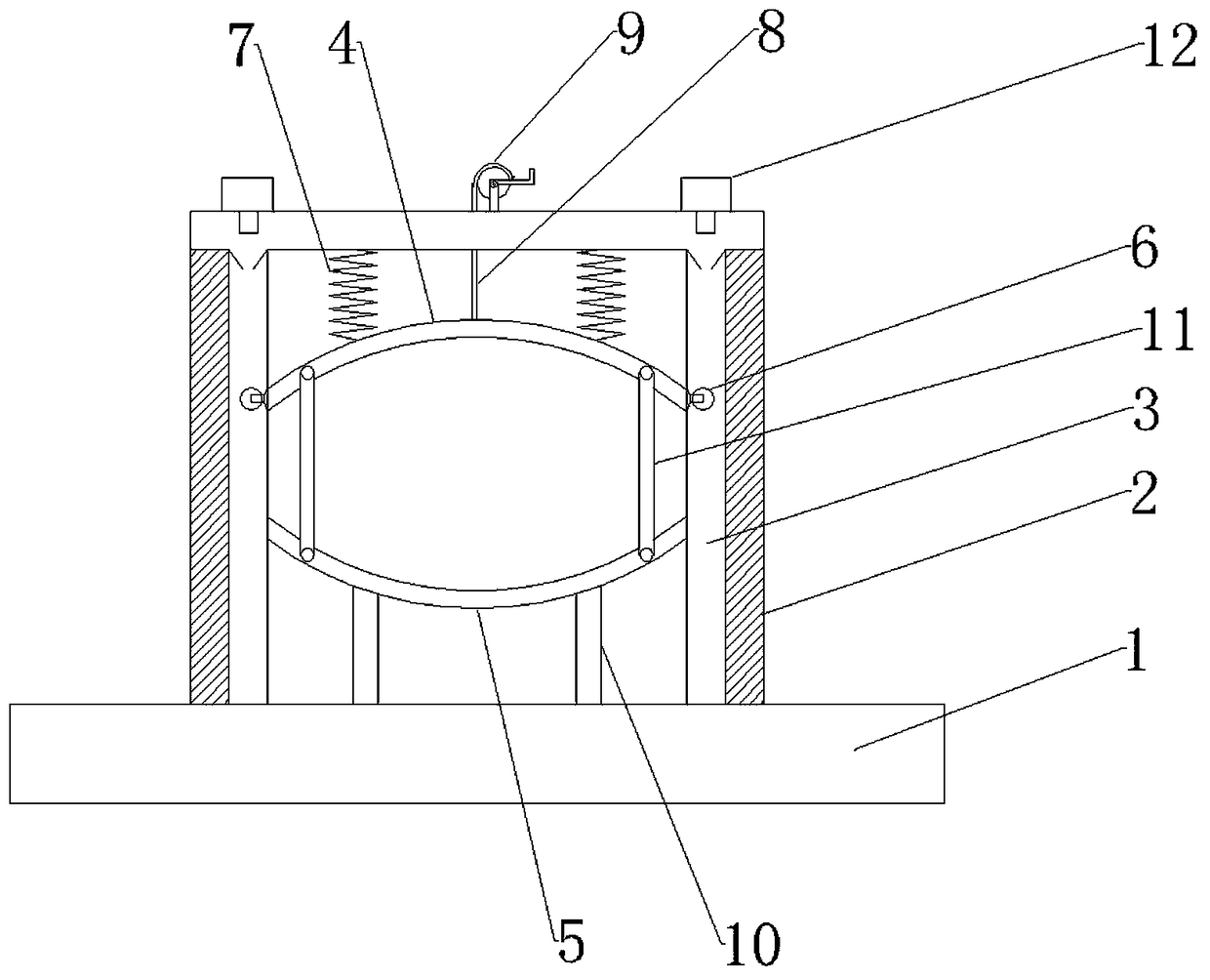
The invention discloses a pipeline installing device in the technical field of mechanical installation. The pipeline installing device comprises a base plate, wherein a gate-shaped frame body is fixed to the base plate, a groove is formed in the inner side of the frame body in the vertical direction, an upper clamping plate and a lower clamping plate are arranged on the inner side of the frame body and are arc-shaped, rollers are arranged at two ends of the upper clamping plate and are connected in the groove in a rolling mode, the upper clamping plate is connected to the top of the frame body through a spring, a traction rope is further connected to the upper clamping plate, a hand wheel is arranged at the top of the frame body, a traction roper penetrates through the top of the frame body and is wound around the hand wheel. The lower clamping plate is fixedly connected to the base plate, a supporting rod is connected between the lower clamping plate and the base, the upper clamping plate and the lower clamping plate are arranged in a mirror symmetry mode, a round cavity for containing a pipeline is formed between the upper clamping plate and the lower clamping plate, and a fastener for fixing the upper clamping plate and the lower clamping plate is further arranged between the upper clamping plate and the lower clamping plate. By adoption of the pipeline installing device, operation is convenient, the pipeline can be firmly fixed, the pipeline does not rotate or slide, and the stability of the pipeline is good.
Description
technical field [0001] The invention belongs to the technical field of mechanical installation, and in particular relates to a pipeline installation device. Background technique [0002] In daily life, the use of pipes is very common, and the installation of pipes refers to clamping or positioning the pipes in the installation pipes. Special equipment or fixtures to meet certain process requirements. During the installation process of the existing pipelines, because the outer surface of the pipelines is cylindrical and easy to roll, it is very inconvenient during the installation process, so the installation workers only have temporary installation devices. Such a method is time-consuming and laborious, and consumes a lot of unnecessary time, thereby affecting the installation progress and reducing work efficiency. [0003] In order to improve the efficiency of pipeline installation, someone has now designed an auxiliary device for pipeline installation, that is, using thi...
Claims
Login to View More Application Information
Patent Timeline
 Patent Type & Authority Patents(China)
IPC IPC(8): B25B11/02
CPCB25B11/02
Inventor 马福寿
Owner 贵州省遵义市永力机电安装有限公司