
Wire arrangement structure of steering engine and robot

A wire structure and steering gear technology, applied in manipulators, program-controlled manipulators, manufacturing tools, etc., can solve problems such as terminal wire damage to normal use of robots

Active Publication Date: 2017-02-22
UBTECH ROBOTICS CORP LTD
View PDF6 Cites 6 Cited by
  • Summary
  • Abstract
  • Description
  • Claims
  • Application Information

AI Technical Summary

Problems solved by technology

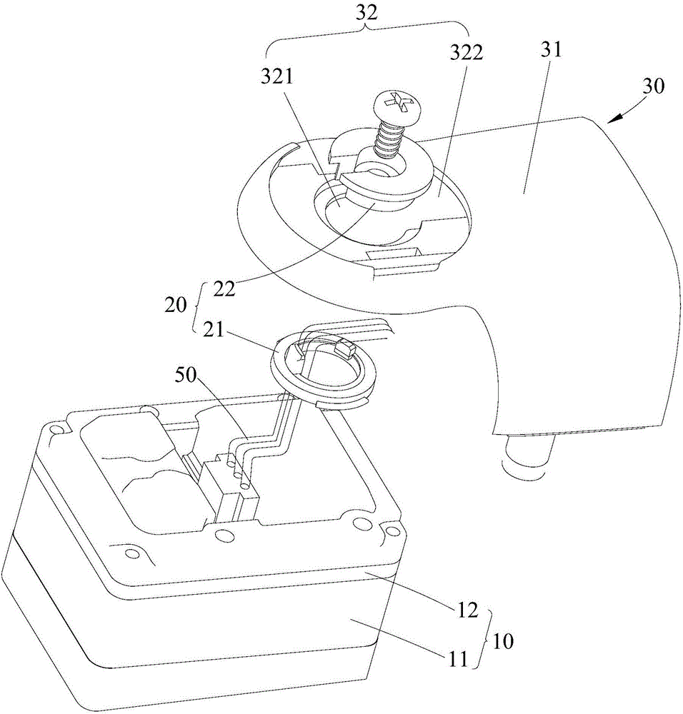
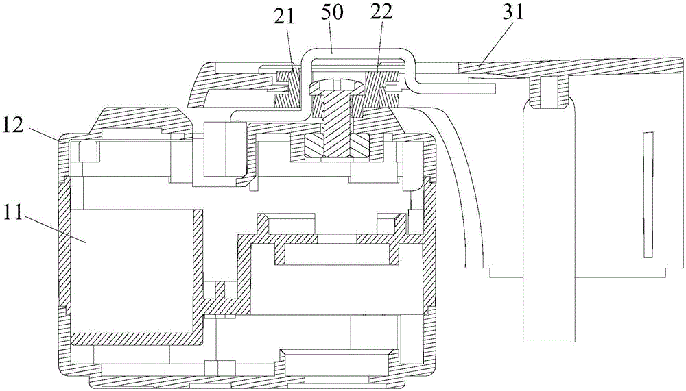
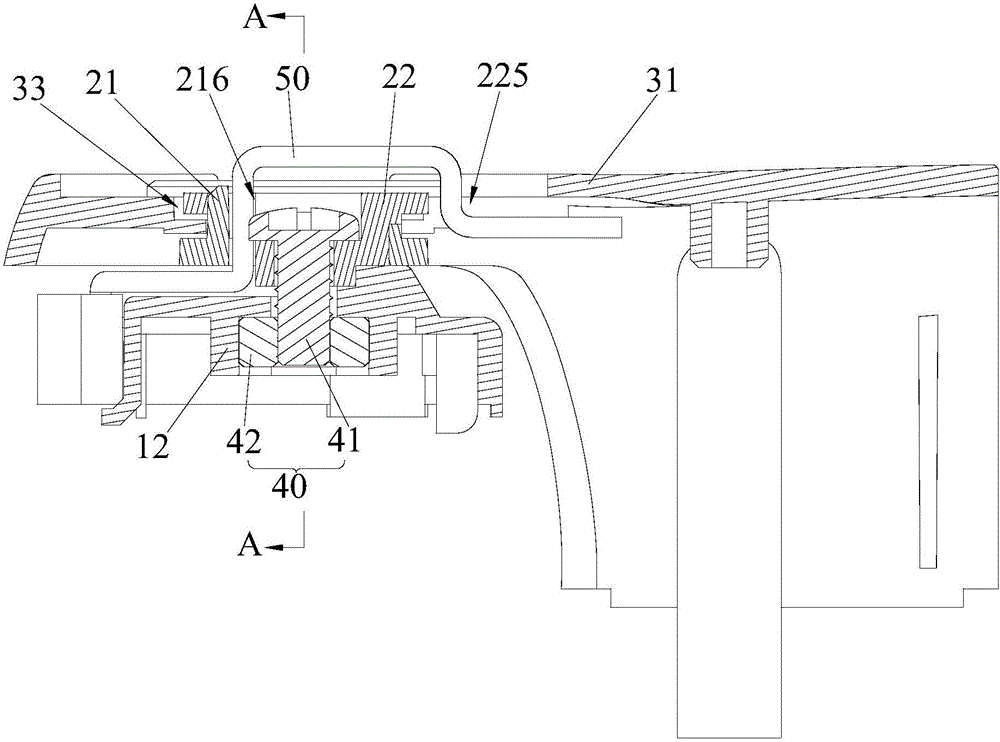
[0003] The purpose of the present invention is to provide a steering gear routing structure and a robot, aiming to solve the problem of terminal wire winding and breaking caused by the rotation of the rotating part relative to the fixed part in the steering gear routing structure existing in the prior art Causes damage to the terminal wires and affects the normal use of the robot

Method used


Image

  • Wire arrangement structure of steering engine and robot
  • Wire arrangement structure of steering engine and robot
  • Wire arrangement structure of steering engine and robot

Examples


Embodiment Construction

[0027] Embodiments of the present invention are described in detail below, examples of which are shown in the drawings, wherein the same or similar reference numerals designate the same or similar elements or elements having the same or similar functions throughout. The embodiments described below by referring to the figures are exemplary and are intended to explain the present invention and should not be construed as limiting the present invention.

[0028] In describing the present invention, it should be understood that the terms "length", "width", "upper", "lower", "front", "rear", "left", "right", "vertical", The orientation or positional relationship indicated by "horizontal", "top", "bottom", "inner", "outer", etc. are based on the orientation or positional relationship shown in the drawings, and are only for the convenience of describing the present invention and simplifying the description, rather than Nothing indicating or implying that a referenced device or element...


PUM


Abstract

The invention provides a wire arrangement structure of a steering engine and a robot comprising the wire arrangement structure. The wire arrangement structure of the steering engine is used for arranging terminal wires led out from the steering engine. The wire arrangement structure of the steering engine comprises a rotating part and a connecting assembly, wherein internal parts of the connecting assembly are matched mutually to form a first wire passing channel through which the terminal wires pass; the rotating part and the connecting assembly are rotatably connected and matched to form a second wire passing channel; and the terminal wires led out from a steering engine body sequentially pass through the first wire passing channel and the second wire passing channel and stretch into the rotating part. The wire arrangement structure of the steering engine avoids the condition that the use of the rotor is affected by the damage of the terminal wires resulting from winding, tensile failure and the like of the terminal wires caused by the rotation of the rotating part.

Description

technical field [0001] The invention belongs to the field of robot design, and in particular relates to a routing structure of a steering gear and a robot. Background technique [0002] At present, when designing a robot, many steering gears are used, and the routing of the terminal wires of the steering gear in the robot shell becomes very complicated, especially the terminal wires between the relative rotating parts in the robot shell. Generally, it is fixed by wire clamp. When the robot is working, the rotating part in the wiring structure rotates frequently relative to the fixed part, and the terminal wire fixed by the wire clamp may rub against other parts or be clamped, which will reduce the life of the terminal wire, or even Direct damage to the motor will affect the normal use of the robot. Contents of the invention [0003] The purpose of the present invention is to provide a steering gear routing structure and a robot, aiming to solve the problem of terminal wi...

Claims


Application Information

Patent Timeline
Patent Type & Authority Applications(China)
IPC IPC(8): B25J9/00
CPCB25J9/0009
Inventor 李冠佑熊友军
Owner UBTECH ROBOTICS CORP LTD
Learn More