
Scraper conveyor with float coal cleaning device
A scraper conveyor and cleaning device technology, which is applied in the field of scraper conveyors, can solve the problems of lowering the transmission power, reducing the effective output power of the geared motor, and falling off, and achieves the advantages of easy cleaning, enhanced effective output power, and stable structure Effect
- Summary
- Abstract
- Description
- Claims
- Application Information
AI Technical Summary
Problems solved by technology
Method used
Image

Examples
Embodiment 1
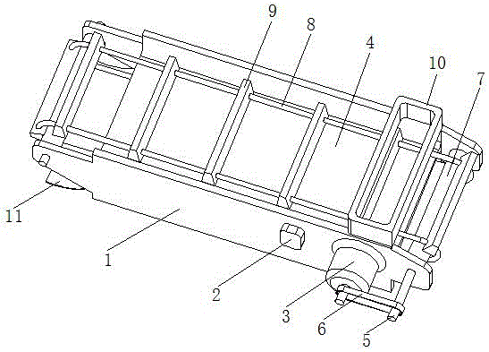
[0024] A scraper conveyor with a floating coal cleaning device, comprising two parallel side frame plates 1 and a wear-resistant bottom plate 4, the two side frame plates 1 are connected and fixed by a wear-resistant bottom plate 4 to form a U-shaped groove Structure; a feed hopper 10 is provided at the upper end of one side of the two side frame plates 1 , and a lower hopper 11 is provided at the lower end of the other side of the two side frame plates 1 .
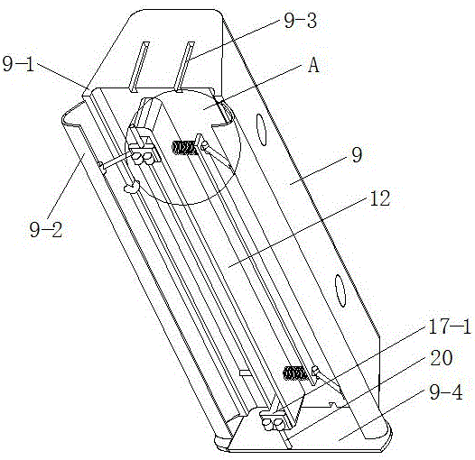
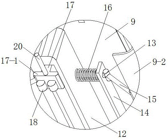
[0025] The shaft holes on the left and right sides of the side frame plate 1 are respectively provided with transmission shafts 5, and a roller 7 that is closely matched or integrally formed with it is arranged on the transmission shaft 5, and the two rollers 7 are connected by two chains 8. transmission, between the two chains 8 there are evenly arranged a plurality of scrapers 9 which are synchronously driven; the shaft end of the transmission shaft on the right side is connected with the output shaft of the reduction mo...
example example 2
[0031] A scraper conveyor with a floating coal cleaning device, comprising two parallel side frame plates 1 and a wear-resistant bottom plate 4, the two side frame plates 1 are connected and fixed by a wear-resistant bottom plate 4 to form a U-shaped groove Structure; a feed hopper 10 is provided at the upper end of one side of the two side frame plates 1 , and a lower hopper 11 is provided at the lower end of the other side of the two side frame plates 1 .
[0032] The shaft holes on the left and right sides of the side frame plate 1 are respectively provided with transmission shafts 5, and a roller 7 that is closely matched or integrally formed with it is arranged on the transmission shaft 5, and the two rollers 7 are connected by two chains 8. transmission, between the two chains 8 there are evenly arranged a plurality of scrapers 9 which are synchronously driven; the shaft end of the transmission shaft on the right side is connected with the output shaft of the reduction mo...
Embodiment 3
[0037]A scraper conveyor with a floating coal cleaning device, comprising two parallel side frame plates 1 and a wear-resistant bottom plate 4, the two side frame plates 1 are connected and fixed by a wear-resistant bottom plate 4 to form a U-shaped groove Structure; a feed hopper 10 is provided at the upper end of one side of the two side frame plates 1 , and a lower hopper 11 is provided at the lower end of the other side of the two side frame plates 1 .
[0038] The shaft holes on the left and right sides of the side frame plate 1 are respectively provided with transmission shafts 5, and a roller 7 that is closely matched or integrally formed with it is arranged on the transmission shaft 5, and the two rollers 7 are connected by two chains 8. transmission, between the two chains 8 there are evenly arranged a plurality of scrapers 9 which are synchronously driven; the shaft end of the transmission shaft on the right side is connected with the output shaft of the reduction mot...
PUM
 Abstract
Description
Claims
Application Information