Vibration conveyor

A technology of vibration conveying and vibrator, which is applied in the direction of vibrating conveyor, conveyor, transportation and packaging, etc. It can solve problems such as unsmoothness, affecting work efficiency, uneven transportation, etc., and achieves the effect of preventing material blockage and ensuring smooth feeding

Inactive Publication Date: 2017-02-22
M & J MACHINERY ENGINEER
View PDF6 Cites 3 Cited by
  • Summary
  • Abstract
  • Description
  • Claims
  • Application Information

AI Technical Summary

Problems solved by technology

[0002] In the prior art, when conveying materials, the auger conveying mechanism is usually used, and the conveying direction of the materials is changed. In the actual application process, the phenomenon of material jams often occurs, and the conveying is uneven and not smooth, which affects the work efficiency.
In order to solve this problem, a vibrator is currently added to the conveying pipeline. The installation of the vibrator generally adopts a suspension structure, which has a relatively large shake and a high height, thus creating a transitional degree of freedom during use, which affects the normal operation. Work demand, reduce work efficiency

Method used


Image

  • Vibration conveyor

Examples


Embodiment Construction

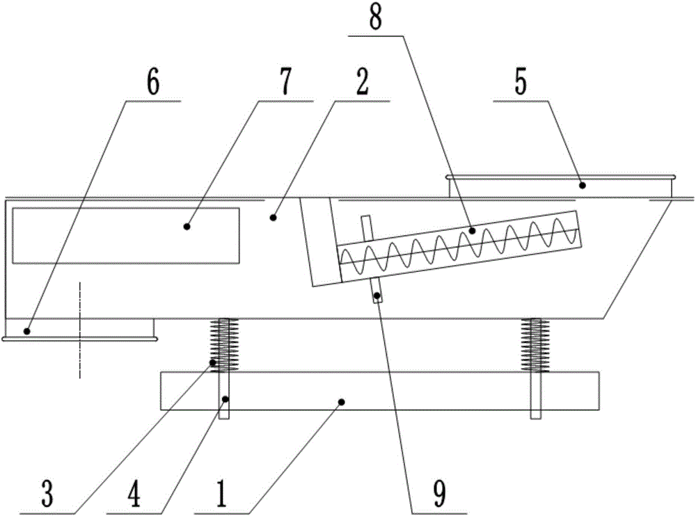
[0012] The specific embodiments of the present invention will be further described below in conjunction with the accompanying drawings.

[0013] Such as figure 1 As shown, the vibrating conveyor of this embodiment includes a delivery channel 2 installed horizontally or obliquely on the base 1, a guide rod 4 with a spring 3 is installed between the delivery channel 2 and the base 1, and one end of the delivery channel 2 is an inlet The feed port 5 has a discharge port 6 at the other end, and a vibrator 7 is built in the conveying channel 2 near the discharge port 6, and a screw conveying shaft 8 inclined to be installed between the feed port 5 and the discharge port 6 is installed.

[0014] Further, in order to further improve the conveying smoothness, the outer wall of the lower end of the screw conveying shaft 8 is provided with a stirring shaft 9 .

[0015] The above examples are preferred implementations of the present invention, and are only used to illustrate the present...


PUM


Abstract

The invention relates to a vibration conveyor which comprises a conveying passage horizontally or obliquely mounted on a base. A guide rod provided with a spring is mounted between the conveying passage and the base, a feeding port is arranged at one end of the conveying passage, a discharging port is arranged at the other end of the conveying passage, a vibration is arranged in the conveying passage close to the discharging port, and a spiral conveying shaft which is arranged obliquely is mounted between the feeding port and the discharging port. The vibrator which is arranged inside is adopted, and the spiral conveying shaft is arranged, so that material blockage can be prevented, and smooth material feeding is ensured.

Description

technical field [0001] The invention relates to the field of packaging machinery, in particular to a vibrating conveyor. Background technique [0002] In the prior art, when conveying materials, the auger conveying mechanism is usually used, and the conveying direction of the materials is changed. In the actual application process, the phenomenon of material jams often occurs, and the conveying is uneven and not smooth, which affects the work efficiency. In order to solve this problem, a vibrator is currently added to the conveying pipeline. The installation of the vibrator generally adopts a suspension structure, which has a relatively large shake and a high height, thus creating a transitional degree of freedom during use, which affects the normal operation. Work demand, reduce work efficiency. Contents of the invention [0003] In view of the above-mentioned problems existing in the prior art, the applicant conducts research and improvement to provide a vibrating conve...

Claims


Application Information

Patent Timeline
IPC IPC(8): B65G27/04B65G27/08B65G27/34
CPCB65G27/04B65G27/08B65G27/34
Inventor 何海英
Owner M & J MACHINERY ENGINEER
Why Eureka
Try Eureka