Gasification Nozzles and Gasifiers

A nozzle and gasification agent technology, which is applied in the coal chemical industry, can solve the problems of clogging, unstable and uneven flame of gasification nozzles, and aggravating the maintenance burden of gasification nozzles.

Active Publication Date: 2018-03-20
CHNA ENERGY INVESTMENT CORP LTD +1
View PDF2 Cites 0 Cited by
  • Summary
  • Abstract
  • Description
  • Claims
  • Application Information

AI Technical Summary

Problems solved by technology

[0004] However, due to the unreasonable structure of the flow divider in the prior art, the material cannot be divided evenly through the flow divider, and powder accumulation and blockage often occur in the structural dead ends of the flow divider
As a result, the gasification nozzle cannot quickly co-flow and eject the material and gasification agent, and the flame of the gasification nozzle is unstable and uneven; which in turn leads to a low carbon conversion rate of the gasification furnace and a large amount of gasification residue
In addition, the gasification nozzle is located in the high-temperature and pressurized operating environment of the gasification furnace, so the maintenance workload is relatively large, and the frequent blockage of the flow divider increases the maintenance burden of the gasification nozzle, resulting in a decrease in the production efficiency of the gasification furnace
Therefore, the gasification nozzle in the prior art needs to be improved

Method used


Image

  • Gasification Nozzles and Gasifiers
  • Gasification Nozzles and Gasifiers
  • Gasification Nozzles and Gasifiers

Examples


Embodiment Construction

[0033] Specific embodiments of the present invention will be described in detail below in conjunction with the accompanying drawings. It should be understood that the specific embodiments described here are only used to illustrate and explain the present invention, and are not intended to limit the present invention.

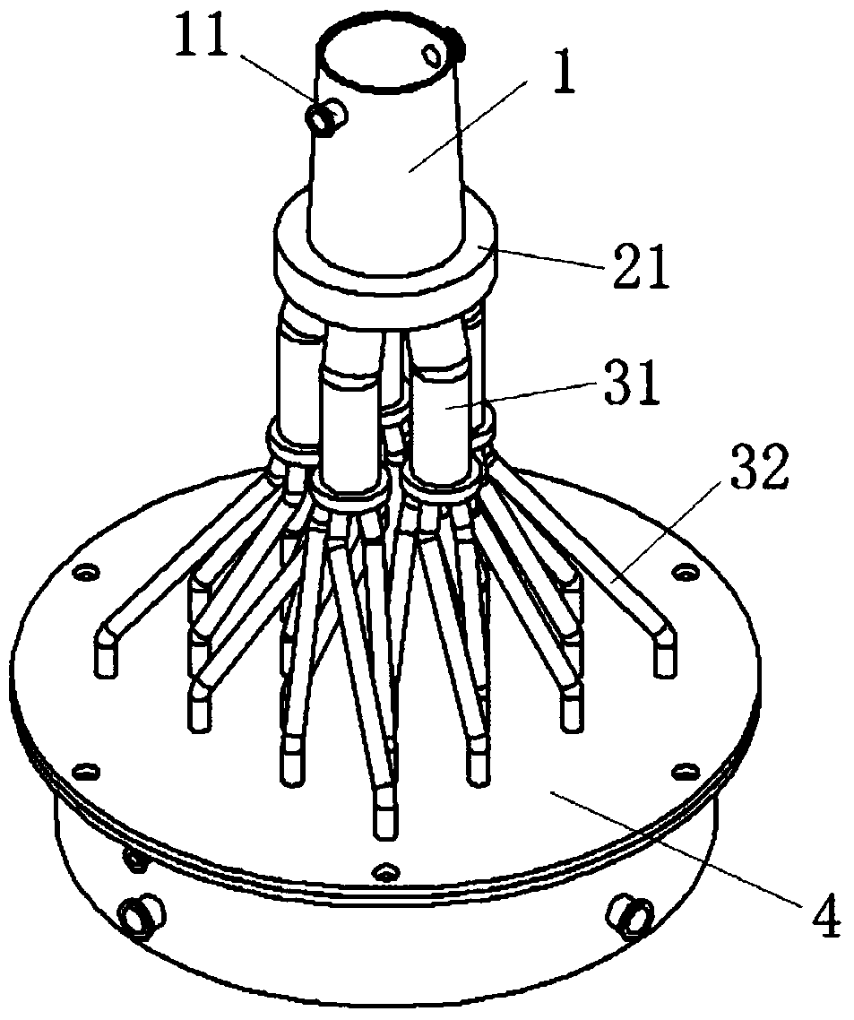
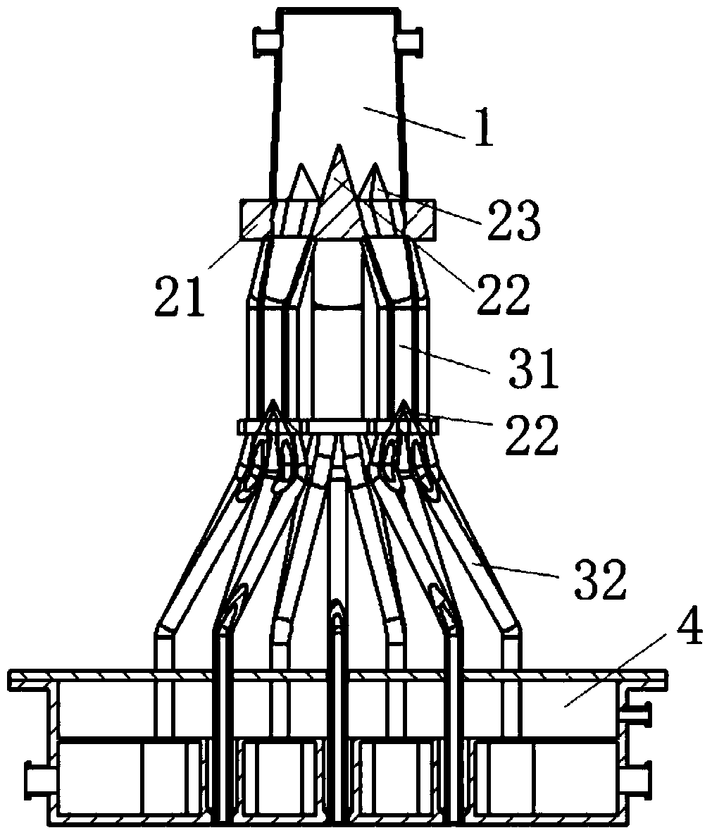
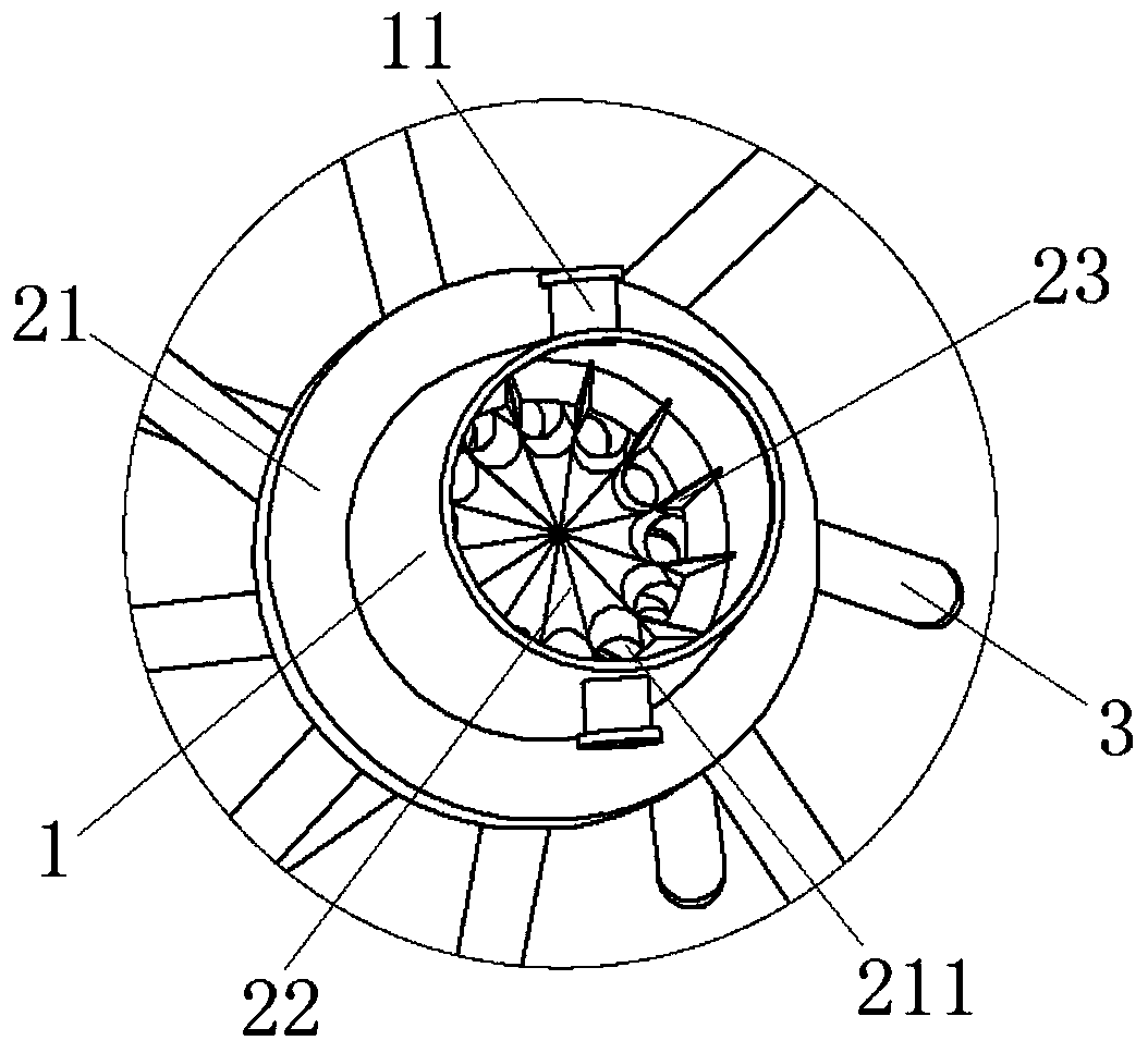
[0034] refer to Figure 1 to Figure 3 , The invention provides a gasification nozzle, which is used to spray materials and gasification agent into the cavity of a gasification furnace in parallel flow. According to an embodiment of the present invention, the gasification nozzle includes a conveying part for conveying materials, and an injection part 4 connected to the end of the conveying part for injecting materials and gasification agent. Wherein, the conveying part includes a conveying main pipe 1 and at least two stages of conveying branch pipes. The material is diverted from the conveying main pipe 1 to a plurality of first-stage conveying branch pipes 31...


PUM


Abstract

The invention discloses a gasification nozzle, which includes a conveying part for conveying materials, and an injection part connected to the end of the conveying part for spraying materials. The conveying part includes a conveying main pipe (1) and at least two stages of conveying branch pipes. The main pipe communicates with the first-stage delivery branch pipe (31) and the adjacent two-stage delivery branch pipes through a flow divider. At least one flow divider includes a base body, and a plurality of through holes (211) are opened on the base body; each flow divider also includes a polygonal pyramid, and each side of the polygonal pyramid is connected with a part of the pipe wall of the delivery main pipe or with two adjacent stages A part of the pipe wall of the upper delivery branch pipe of the delivery branch pipe respectively encloses the guide surface of each through hole, and the side surface of the polygonal pyramid covers the top surface of the base body. The invention also discloses a gasifier provided with the above-mentioned gasification nozzle. The invention can evenly divide the flow of materials in the gasification nozzle, and prevent the powder accumulation and clogging of the materials, thereby improving the production efficiency of the gasification furnace.

Description

technical field [0001] The invention relates to the field of coal chemical industry, in particular to a gasification nozzle and a gasifier. Background technique [0002] Coal gasification technology is the basis for the development of coal-based chemicals, liquid fuels, IGCC power generation, hydrogen production and other processes, and is a leading technology in the coal chemical industry. Due to the rapid development of industries such as synthetic ammonia, methanol, dimethyl ether, coal-to-oil, and coal-to-olefins, China's coal gasification process is rapidly transitioning from the old-fashioned UGI furnace lump coal intermittent gasification to the advanced pulverized coal gasification process. There is a strong demand for various types of pulverized coal gasification technology and equipment. [0003] The gasification reaction is carried out under high temperature and pressure conditions. Among them, the gasification nozzle is used to make the materials such as coal p...

Claims


Application Information

Patent Timeline
Patent Type & Authority Patents(China)
IPC IPC(8): C10J3/50B05B1/26
CPCY02E20/18
Inventor 方薪晖刘臻冯子洋陈薇卢洪
Owner CHNA ENERGY INVESTMENT CORP LTD
Why Eureka
Try Eureka