Eureka AIR delivers breakthrough ideas for toughest innovation challenges, trusted by R&D personnel around the world.

Roller shaft device for machining steel belt

A technology of rollers and steel belts, which is applied in the field of steel belt processing roller devices, can solve problems such as easy slipping, and achieve the effects of enhancing safety, reducing the probability of slipping, and facilitating disassembly

Active Publication Date: 2017-02-22
JIAXING BIANKA BAG & CASE
View PDF5 Cites 0 Cited by
  • Summary
  • Abstract
  • Description
  • Claims
  • Application Information

AI Technical Summary

Problems solved by technology

[0004] Aiming at the deficiencies of the prior art, the present invention provides a steel strip processing roller shaft device, which has the advantage of being fixed and easy to disassemble, and solves the problem of easy slippage caused by the layer-by-layer set-up of traditional roller shafts

Method used


Image

  • Roller shaft device for machining steel belt
  • Roller shaft device for machining steel belt

Examples


Embodiment 1

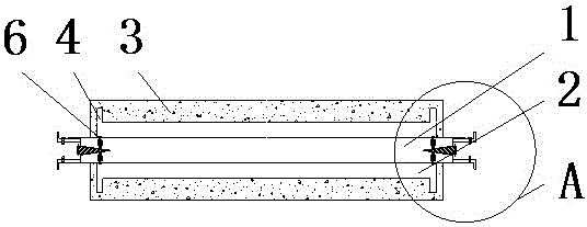
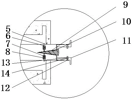
[0029] see figure 1 with figure 2 , the whole device can be put into the corresponding position, and the device can be locked by the protruding structure of the connecting ring 11, and the nut 14 can also play a role of clamping. At this time, the external steel belt rotates to drive the whole device to rotate.

Embodiment 2

[0031] see figure 1 with figure 2 , the output shaft of the corresponding power source can be inserted into the inside of the connection block 11, and the nut 14 is pressed down to fix the output shaft. This is the external power to drive the roller shaft device to rotate so as to drive the steel belt.

[0032] When in use, the steel belt is placed outside the pressure-bearing layer 3, the pressure-bearing layer 3 is squeezed, and at the same time the steel belt moves to drive the entire device to rotate.

[0033] To sum up, the steel strip processing roller device, by setting the limit ring 4, can make the pressure-bearing layer 3 be better fixed after receiving pressure, reduce the probability of slippage, and enhance safety. The groove 5 and the connecting rod 6 can use the pressure of the screw 10 to stably connect the roller shaft 1 to the roller 2 without slipping off, and can be easily disassembled, and the connection block 11 is provided to better meet various needs ...


PUM


Abstract

The invention discloses a roller shaft device for machining a steel belt. The roller shaft device comprises a roller shaft, wherein a roller sleeves the outer part of the roller shaft; a pressure bearing layer sleeves the outer part of the roller; limiting rings are fixedly mounted at outer parts of two ends of the roller; a through groove is formed in the inner side of the roller; an inserting rod is movably mounted in the through groove; an anti-releasing ring is movably mounted at the outer part of the lower part of the inserting rod; a spring sleeves the outer part of the inserting rod; screw holes are formed in two sides of the roller shaft; a screw is movably mounted in the screw holes; a connecting block is pressed on the lower part of the top of the screw; a bolt is movably mounted at one end, stretching out of the roller shaft, of the connecting block; and a storage groove is formed in the lower part of an inner wall of the connecting block. According to the roller shaft device for machining the steel belt, the through groove and the inserting rod are arranged, and the roller shaft and the roller can be stably connected through utilizing pressure of the screw, do not slip and are also convenient to detach; and the connecting block is arranged so that the roller shaft device for machining the steel belt can meet various types of requirements very well.

Description

technical field [0001] The invention relates to the technical field of steel structure processing, in particular to a steel strip processing roller shaft device. Background technique [0002] In the process of steel processing, a large number of rollers are needed to arrange and transport the steel belt. Although the rollers are mainly used in conjunction with other equipment, the rollers themselves are also a very important part. The current roller connections are generally Layer-by-layer suits, but the structure of the suit will easily cause the entire roller shaft to slip off, which will cause danger and affect the safety of the operator. Contents of the invention [0003] (1) Solved technical problems [0004] Aiming at the deficiencies of the prior art, the present invention provides a steel strip processing roller shaft device, which has the advantages of being fixed and easy to disassemble, and solves the problem of easy slippage caused by the layer-by-layer sheath...

Claims


Application Information

Patent Timeline
IPC IPC(8): B65G39/02
CPCB65G39/02
Inventor 陆毛华
Owner JIAXING BIANKA BAG & CASE
Why Eureka
Eureka Blog
Learn More